Dynamic Power Backoff Algorithm Validation for Array Exposure Compliance
Validate dynamic power backoff algorithms using sub-millisecond conducted power logging alongside spatial field scans to pass regulatory pre-approval audits.
Mechanism
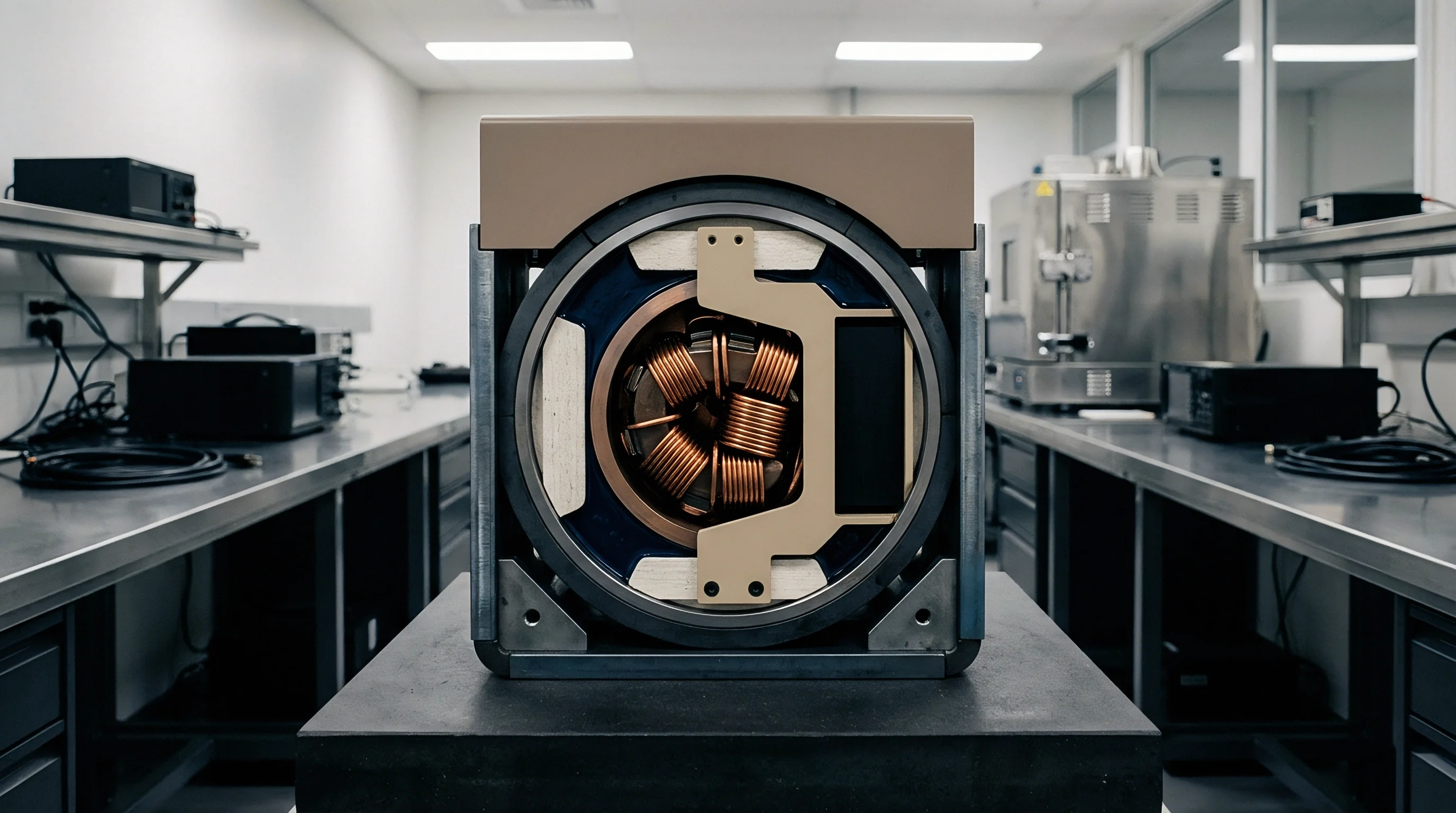
Active phased-array transceivers in millimeter-wave and sub-6 GHz handsets regulate radiofrequency exposure using time-averaged absorption controllers. Because multi-element arrays focus energy into narrow, steerable beams, operating near human tissue can drive localized Specific Absorption Rate (SAR) or Incident Power Density (IPD) past regional thresholds unless the RF front-end throttles output power.
Dynamic backoff routines track transmission levels across defined averaging windows, trimming amplifier drive during sustained transmission. Firmware state machines calculate discrete backoff steps directly from the active beamforming vector, operating duty cycle, and live sensor inputs.

Time Averaged Power Backoff Operational Logic
International standards cap localized SAR and absorbed power density over moving time windows ~ typically 100 seconds for sub-6 GHz bands and 4 seconds for millimeter-wave frequencies above 24 GHz. To track this, time-averaged exposure controllers run a sliding-window ring buffer of conducted power measurements.
Sustained high-power transmission pushes total windowed energy toward regulatory thresholds. The controller evaluates normalized exposure across all active bands and spatial beam states, applying deterministic backoff steps before cumulative exposure reaches the normalized 1.0 limit. Trimming power amplifier gain or switching active element combinations keeps spatial absorption compliant without dropping the link.
Dynamic power backoff controllers maintain regulatory compliance by dropping transmit power before cumulative energy absorption exceeds the running time window threshold.

Sensor Interlocks and Beamforming Array State Switching
Handsets combine capacitive pads, optical sensors, and country-code flags to detect when the device nears human tissue. Triggering a proximity sensor shifts binary state inputs, prompting immediate state-machine transitions.
Control algorithms map each array index and steering vector against a factory-calibrated power lookup matrix. When an active beam aligns peak radiated energy toward an occupied tissue boundary, the controller applies a backoff factor within tens of milliseconds, overriding peak throughput targets to remain compliant.
- Beam Codebook Mismatch occurs when stored radiation patterns in non-volatile memory fail to account for destructive phase combining between adjacent array patches.
- Sensor Debounce Latency delays power reduction when a capacitive proximity sensor takes longer than eighty milliseconds to validate skin contact during rapid movement.
- Time Window Buffer Overflow happens when sustained transmit bursts overflow the dynamic averaging buffer, causing the controller to fall back to uncalibrated full power.
- Thermal Throttling Override drops array drive for junction protection while passing an invalid regulatory backoff state to the host operating system.
Failing to throttle transmission within the certified window invalidates SAR compliance filings and risks impoundment or recall of hardware shipments at ports of entry.

Bench
Validating dynamic RF exposure requires synchronizing conducted power logging with spatial field scans inside shielded chambers. While conventional SAR compliance relies on fixed maximum power to establish worst-case distribution, dynamic testing must capture rapid power adjustments across live call box handovers.
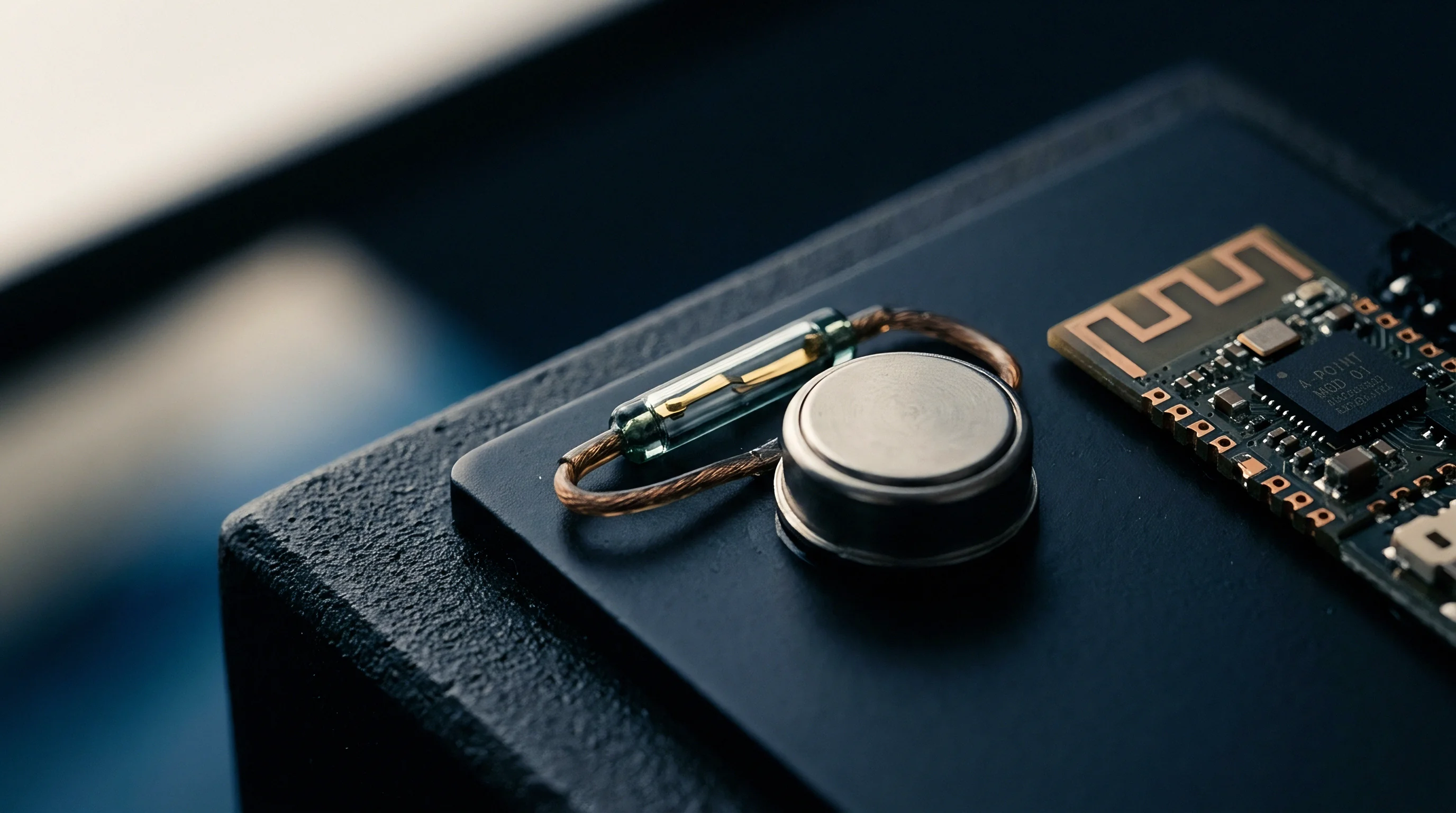
Directional couplers tapped into antenna feedlines route transmit power to high-speed sampling power meters, while electric field probes or optical sensor arrays measure absorption in liquid phantoms or planar mmWave scanning grids. Correlating conducted power timestamps with spatial probe data confirms algorithm response timing.

Simulated Base Station and RF Power Logging Integration
Call boxes link directly with the device under test, commanding output power steps across active channels. Test automation drives the link to maximum power while cycling beam vectors across sub-6 GHz and millimeter-wave array profiles.
Directional couplers sample forward RF power above 100 Hz, capturing conducted transients at sub-millisecond resolution that standard averaging meters blur. Aligning power drops with call-box handovers confirms that backoff steps trigger within defined timing margins.
SAR and Power Density Transient Evaluation
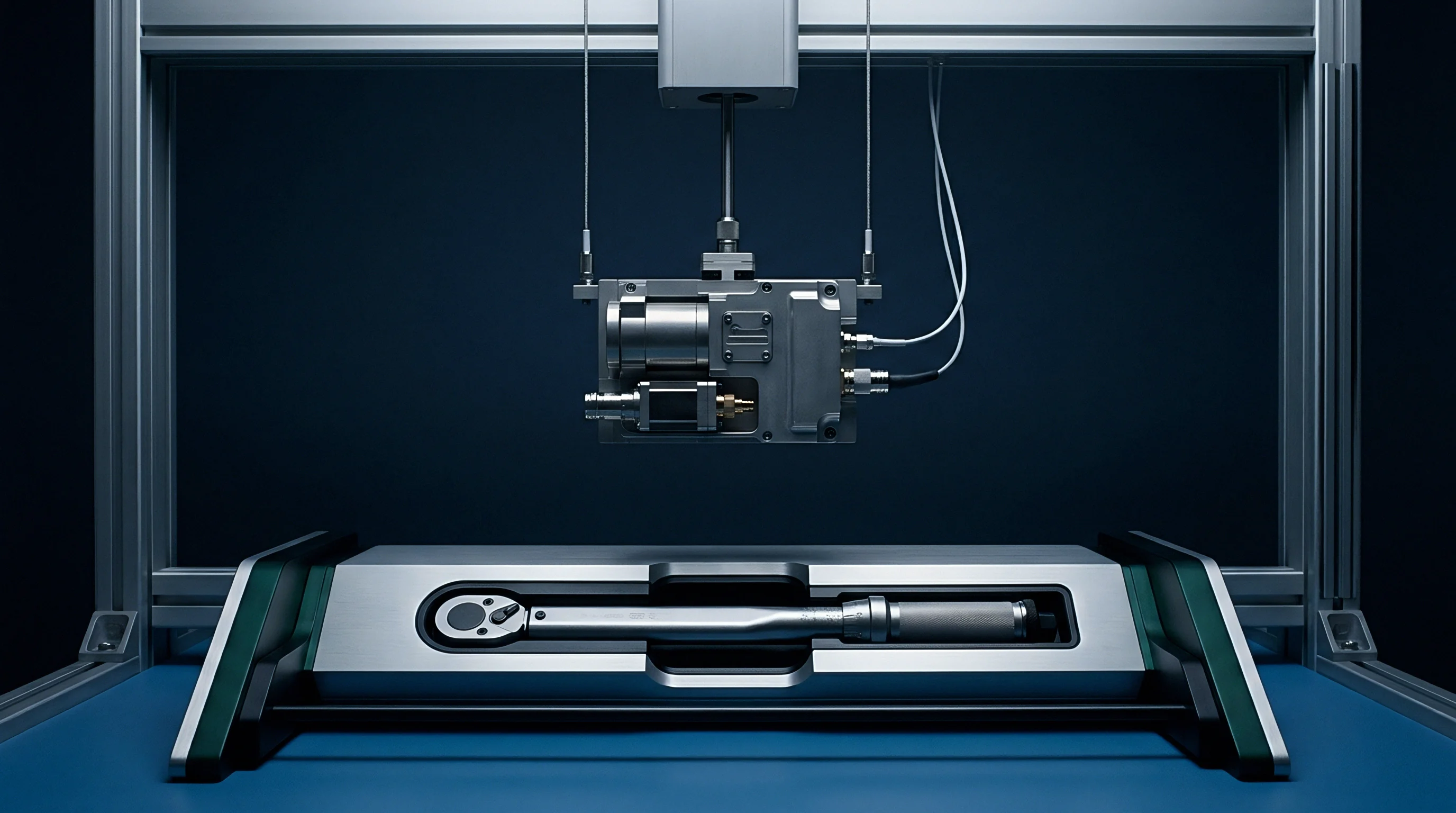
Robotic field probes map local absorption while automated scripts rotate through antenna beam vectors. Under phantom shells, fast-scanning planar sensor arrays capture instantaneous energy distribution across transient power shifts.
| Jurisdiction | Standard Designation | Windowing Interval | Sampling Rate | Special Audit Requirement |
|---|---|---|---|---|
| United States | FCC KDB 447498 D04 / KDB 388624 | 100s sub-6 GHz / 4s mmWave | 100 Hz | Mandatory Pre-Approval Guidance submission |
| Canada | ISED RSS-102 SPR-004 | 100s sub-6 GHz / 4s mmWave | 100 Hz | Technical Acceptance Certificate audit |
| European Union | EN 50665 / IEC IEEE 62209-1528 | 360s sub-6 GHz / 120s mmWave | 10 Hz | Notified Body assessment for dynamic algorithms |
| Japan | MIC Annex 45 / IEC PAS 63184 | 360s sub-6 GHz / 4s mmWave | 10 Hz | Registered Certification Body verification |
Millimeter-wave evaluations rely on free-space reconstructive scanning between 24 GHz and 48 GHz. Probes positioned within two millimeters of the housing map incident power density during beam transitions, verifying that spatial peaks drop in direct proportion to conducted power reductions.
Conducted RF power logging at sub-millisecond intervals during beam steering sequence changes isolates latency spikes that breach spatial peak limits.
Unannounced beam backoff failures often trace to unaccounted thermal calibration drift within chipset front-end firmware.
Firmware
Embedded baseband processors handle exposure control loops directly, combining live sensor interrupts with active beam indices against backoff tables in non-volatile memory. Hardware interrupt lines feed raw capacitance readings straight into the power management thread.
The controller tracks transmit history in ten-millisecond increments, computing sliding-window power integrals across multi-SIM channels and aggregated carrier combinations. When combined transmission nears exposure limits, firmware forces pre-programmed backoff vectors, overriding data-rate demands.

Can Software Backoff Algorithms Pass PAG without Conducted Power Logs?
Federal Communications Commission technical review teams require time-domain power logs recorded alongside spatial field scans. Securing approval through Pre-Approval Guidance procedures demands complete documentation of dynamic execution profiles.
Submissions lacking synchronized conducted power logs face immediate administrative rejection. Static field scans establish spatial peaks, but cannot verify backoff response timing. Regulators require continuous conducted plots across the full window to confirm transitions execute as calculated.
- Inject call box signaling commands to drive the radio to maximum transmit power on its highest frequency channel.
- Trigger capacitive or optical sensors using a tissue phantom to simulate direct contact.
- Log the transient power drop on a synchronized meter to confirm attenuation takes effect within fifty milliseconds.
- Cycle through all codebook beam indices while maintaining the proximity trigger.
- Verify that cumulative radiated energy across the sliding evaluation window remains below the authorized exposure ceiling.

Power Lookup Tables and State Machine Verification
Non-volatile memory tables map transmit state vectors to digital-to-analog drive setpoints, with factory power offsets flashed during production calibration.
FCC KDB 388624 clause 4 specifies that dynamic power control validation reports must include continuous conducted power plots alongside time-averaged exposure calculations.
Firmware validation stresses state machine behavior by corrupting sensor data streams and forcing thread timeouts. Robust implementations default to maximum power backoff whenever sensor links drop or buffer corruption occurs.
Whether harmonized international standards will eventually allow machine-learning models to update backoff tables without chamber revalidation remains an open question among certification bodies.
Approval
Securing market access for active antenna systems requires proving compliance across worst-case beam vectors. Certification dossiers must combine operational algorithm descriptions and software security disclosures with comprehensive chamber scan data.
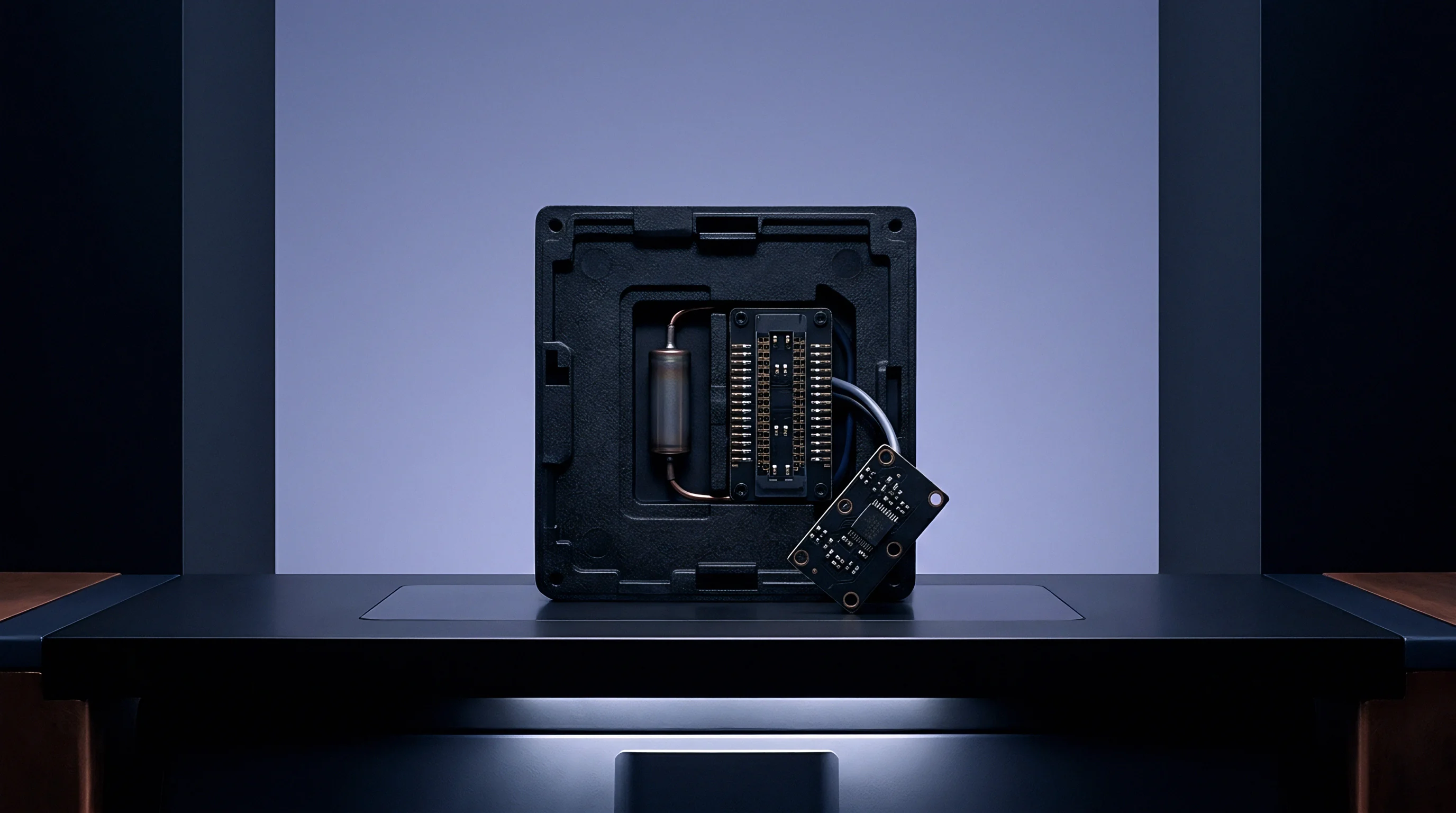
Modular grants complicate system integration. OEMs incorporating certified modules must revalidate dynamic backoff performance within the final enclosure, where housing plastics, sensor placement, and internal shielding alter radiated patterns and shift factory lookup calibrations.
Pre-Approval Guidance and Technical Dossier Requirements
Filings under dedicated inquiry codes require complete algorithm specifications alongside production calibration logs, submitted through administrative review tracks before grants issue.
| Market | Regulatory Filing Mechanism | Required Technical Artifacts | Standard Review Timeline | Mandatory Re-filing Trigger |
|---|---|---|---|---|
| United States | KDB 388624 PAG / C2PC Filing | Time-domain conducted plots, algorithm state descriptions, DASY scan files | 6 to 10 Weeks | Power backoff table edit exceeding 0.5 dB |
| Canada | ISED RSS-102 SPR-004 TAC | SAR scan data, dynamic timing logs, sensor operational proof | 4 to 8 Weeks | Proximity sensor trace layout modification |
| European Union | RED Article 3.1a EU Type Exam | Technical Construction File, Notified Body Risk Opinion, EN 62209 data | 3 to 5 Weeks | Baseband firmware power management code revision |
| Japan | MIC Ordinance 38 Article 2 | RCB Audit report, checksum declaration, static and dynamic SAR scans | 4 to 6 Weeks | Maximum conducted output power increase |
Submissions must document software security controls ensuring end users cannot modify power registers. Certification bodies review binary checksum routines to confirm over-the-air firmware updates preserve approved power backoff tables.

Permissive Changes and Host Integration Obligations
Packaging a certified module into an end-device housing alters antenna gain and shifts capacitive sensing thresholds, requiring formal change assessments under permissive change rules.
Modifying antenna element geometry or dielectric enclosure materials invalidates existing modular dynamic power grants and requires a permissive change submission.
- Antenna Separation Distance verification determines if altering internal component layouts breaches the spatial boundary evaluated in the modular certification grant.
- Enclosure Permittivity Shift testing identifies whether new housing plastics absorb RF energy unevenly and distort array phase relationships.
- Power Table Checksum Audit compares host firmware binary hashes against values recorded in the original laboratory test report.
- Proximity Sensor Overlay Check evaluates if metallized coatings or internal RF shielding reduce capacitive detection sensitivity.
ETSI EN 301 893 clause 4.2.6 mandates that adaptive power control documentation detail software security measures that prevent user access to regulatory power backoff tables.

Margin
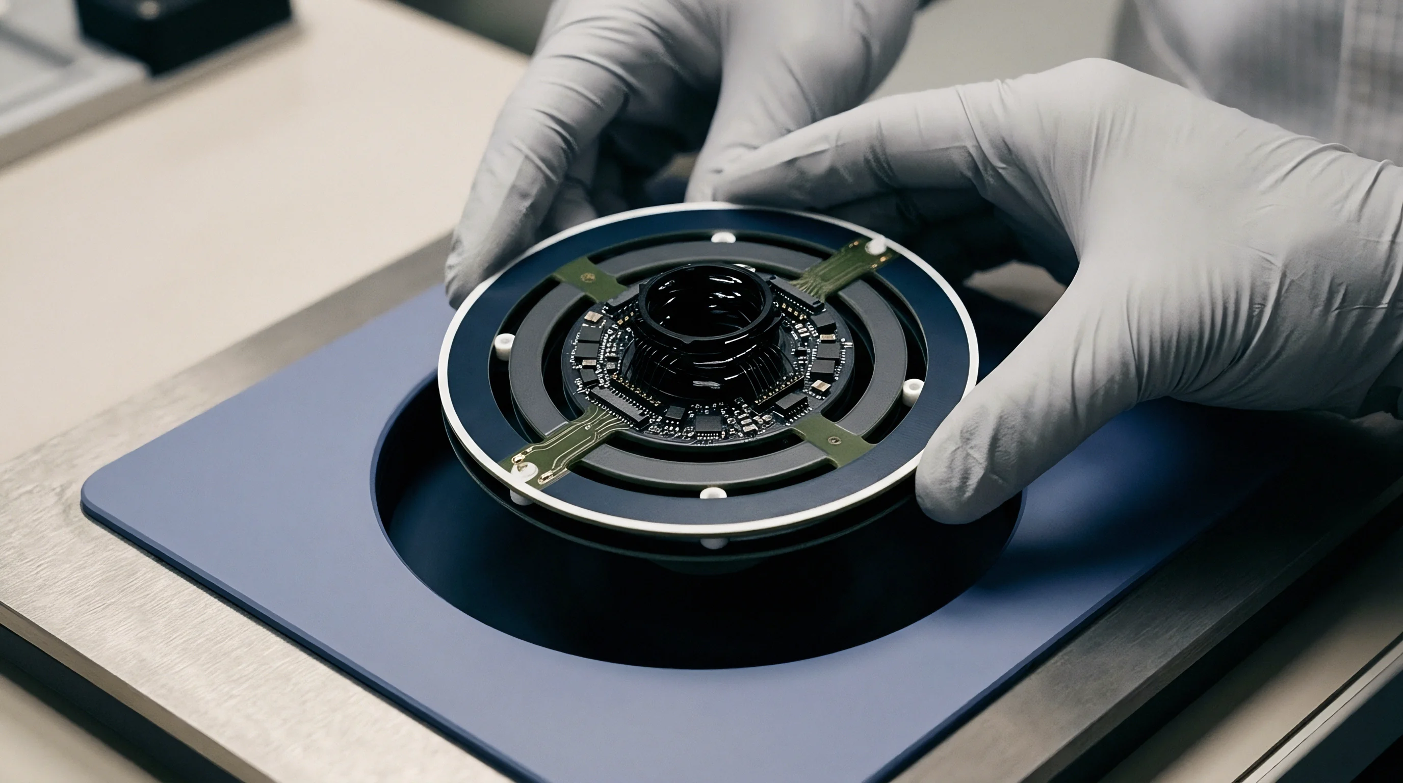
Production yield depends on maintaining deliberate backoff margins during mass assembly. Calibrating backoff thresholds too close to statutory limits leads to batch failures under routine manufacturing drift: silicon lot spread, antenna impedance variation, and PCB dielectric tolerances shift radiated power by up to 0.8 dB.
Engineering teams build software guard bands into lookup tables to absorb production variations. Operating with defined headroom ensures tail-distribution units pass post-market audit sampling without risking import holds or enforcement actions.

Commercial Retest Economics and Laboratory Time Allocation
Chamber time for millimeter-wave power density scans carries substantial costs. Accredited labs charge between $1,800 and $3,500 per day for automated SAR and mmWave chambers. A full validation suite across sub-6 GHz and 28 GHz arrays can consume 80 chamber hours, exceeding $25,000 in direct lab fees.
Certification failures escalate costs rapidly. On a run of 50,000 devices equipped with 5G mmWave modules and a $120 BOM cost ($6,000,000 total batch value), a compliance failure during agency audits immediately halts shipping.
Re-calibrating firmware tables and repeating chamber scans across 16 beam states takes 40 additional chamber hours ($12,000). Expedited Notified Body fees add $18,000. At an 8 percent annual capital holding rate on $6,000,000 ($1,315 daily), a four-week launch delay accumulates $36,820 in capital charges alongside $30,000 in test and filing fees, totaling $66,820 in unbudgeted launch costs.
Applying dynamic backoff thresholds with a 0.8 dB operating margin protects production batches against hardware drift without sacrificing link performance.