Meaning
Standard test methods published under ASTM B539 establish procedures for measuring contact resistance in electrical connections, separable connectors, and relay contacts under both low-current dry-circuit conditions and higher current loads. Measurements conducted under astm b539 quantify resistance across mated conductive surfaces without puncturing insulating tarnish films or altering the microscopic contact asperities. The test protocol stops applying when evaluating bulk volume resistivity of raw wire stock, continuous welded joints, or non-conductive dielectric media where no distinct contact interface exists.
Measurement Protocol
Test procedures codified within the document specify four-wire Kelvin sensing connections to cancel out test-lead resistance and fixture contributions. Circuit instrumentation must restrict the open-circuit voltage to twenty millivolts or less during dry-circuit evaluations, preventing electrical breakdown of ultra-thin surface oxides or chemical films that form on separable mating interfaces. Current levels remain capped at one hundred milliamperes.
Microscopic contact spots, known as a-spots, remain intact throughout the test window under these constrained electrical boundaries. When testing high-current power connectors, alternate procedures defined in the standard allow higher test currents up to rated values to observe Joule heating effects. Resistance changes across environmental conditioning cycles appear clearly in milliohm-level records, establishing whether plating wear or stress relaxation has compromised the interface.
Fixture Interface
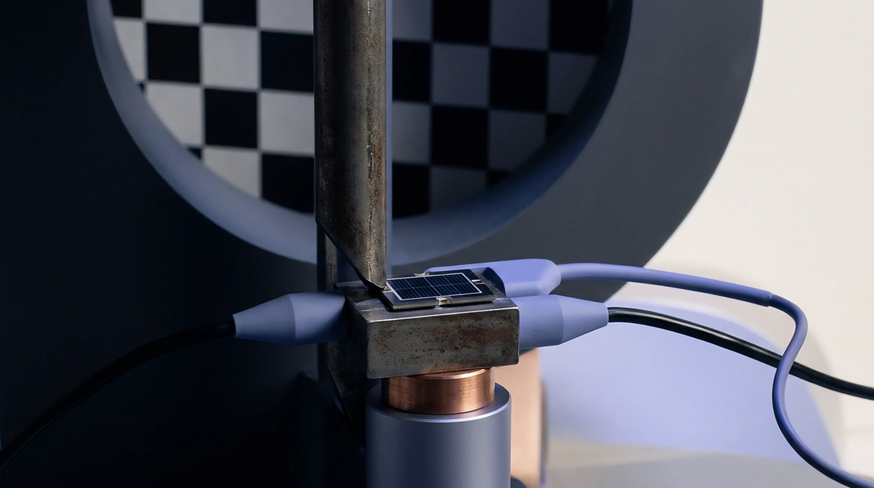
Physical alignment fixtures and probe placements govern the consistency of results obtained across differing test stations. Probe tips must land within specified millimetric distances from the actual contact mating zone to avoid introducing bulk terminal resistance into the interface measurement. Terminal geometries often complicate Kelvin probe placement on miniaturized board-to-board headers or spring contacts.
Test fixturing must avoid applying extraneous clamping force or inducing relative motion between mated terminals during probe engagement, because micro-motion easily punctures contact films and produces falsely low readings.
Handover Criterion
Acceptance criteria derived from qualification plans establish maximum allowable resistance shifts following thermal shock, mixed flowing gas exposure, or vibration sequences. Production handover documentation relies on baseline values established before stress testing alongside post-exposure deltas. Connectors exhibiting shifts greater than ten milliohms or exceeding double their initial resistance fail qualification under standard reliability thresholds.
Mechanical integrity of spring elements directly correlates with stable milliohm values across the product life cycle.