Silicon Substrate Surface Conduction Mitigation in High Resistivity RF Transceivers
Trap-rich polysilicon layers suppress parasitic surface conduction in high-resistivity silicon transceivers, lowering second harmonics below -85 dBc at +25 dBm RF input.
Inversion
Charge Accumulation at the Dielectric Interface
Fixed positive ionic states in thermally grown silicon dioxide pull mobile negative charge carriers directly toward the upper surface of high-resistivity bulk silicon. High-resistivity substrates produced through float-zone or advanced Czochralski growth show intrinsic bulk resistivities from 1000 to 10000 ohm-centimeters. Oxidation cycles during silicon-on-insulator wafer fabrication generate fixed dielectric state densities between 1 times 10 to the 11th power and 5 times 10 to the 11th power per square centimeter.
This buried interface charge creates an electric field that projects into the substrate, bending energy bands downward so mobile electrons gather beneath the oxide layer in a narrow, highly conductive sheet.
This layer acts as a parasitic conducting channel parallel to overlying radio frequency circuit elements. Interface sheet resistance drops from a bulk baseline above 100 kilohms per square to between 0.5 and 5 kilohms per square. High-frequency signals propagating through the transceiver couple capacitively through the buried oxide into this conductive plane, creating a substrate path that increases passive insertion loss, lowers spiral inductor quality factors, and degrades isolation between adjacent transmitter and receiver blocks.
Oxide charge traps accumulate mobile electrons at the substrate surface regardless of bulk silicon purity.
Effective substrate resistivity drops sharply with signal frequency. While the bulk silicon maintains its specified resistance under DC bias, high-frequency alternating fields modulate mobile electron concentration within the narrow accumulation zone. Measured at 2.4 gigahertz under standard planar configurations, effective resistivity falls below 50 ohm-centimeters, breaking the RF isolation expected from high-resistivity wafers.

Frequency Dependent Loss Behaviors
Radio frequency signals degrade over unmitigated surface channels because energy dissipates directly within the accumulated carrier layer. Dielectric displacement current converts into conduction current through Ohmic dissipation in this thin conductive sheet, with total loss scaling directly with surface carrier mobility and interface electron density.
- Parasitic Capacitive Shunting offers a low-impedance high-frequency route from active RF nodes straight into the conductive surface channel, bypassing intended circuit barriers.
- Effective Resistivity Collapse cuts high-frequency substrate impedance from thousands of ohm-centimeters to tens of ohm-centimeters, raising baseline RF signal attenuation.
- Substrate Sub-GHz Crosstalk lets output stage transmit power propagate laterally through the accumulated carrier sheet into sensitive low-noise receiver circuits.
- Inductor Quality Factor Degradation adds parasitic resistance through induced surface eddy currents, reducing passive matching network efficiency.
Leaving this interface accumulation layer unsuppressed forces transceivers to operate with 0.4 to 1.2 decibels of extra front-end insertion loss, degrading receiver noise figures and drawing additional power from amplifier supplies.

Grain
Polysilicon Trap Density and Defect Physics
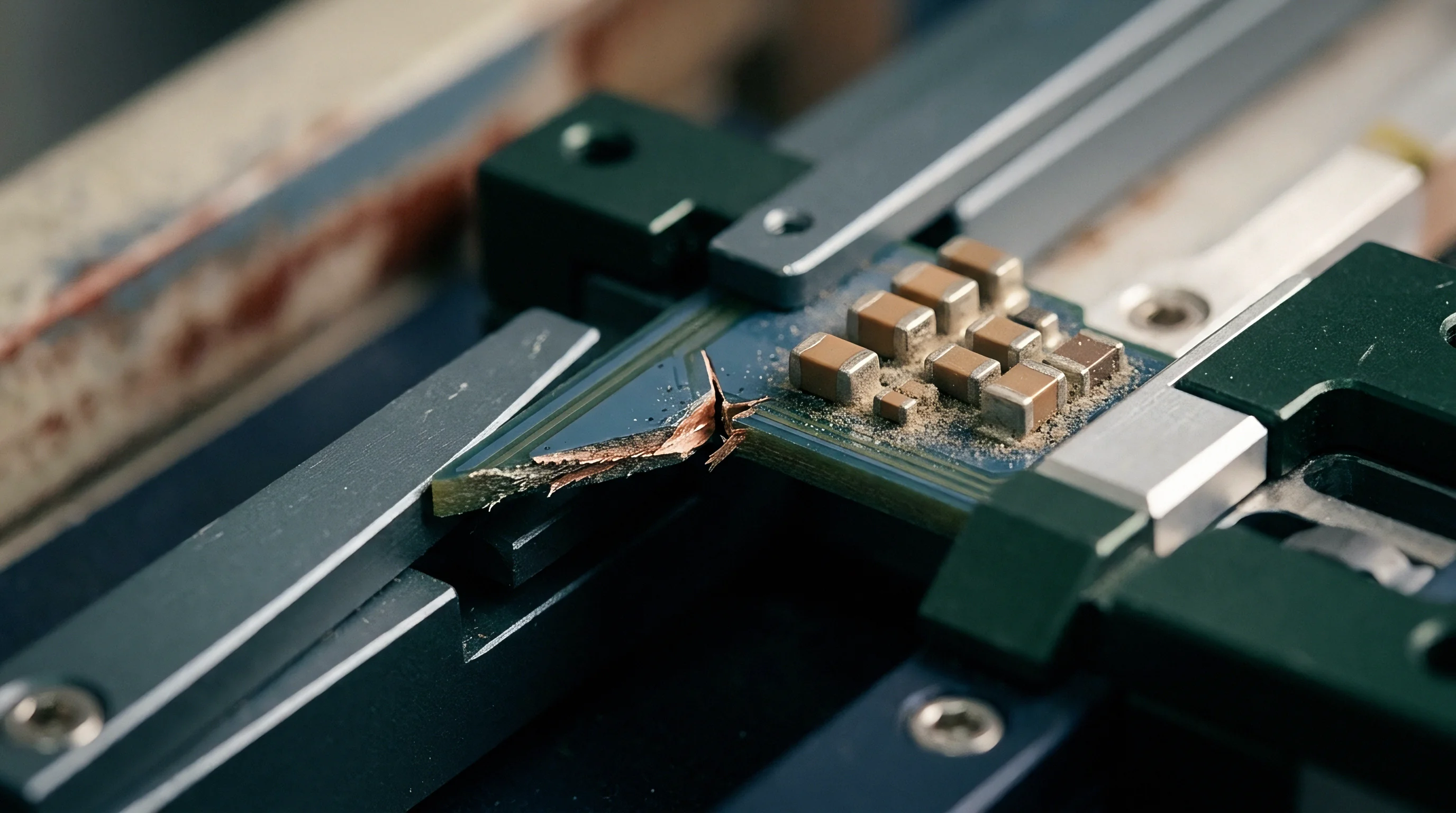
Depositing an undoped polysilicon layer directly on the high-resistivity bulk wafer disrupts lattice order before buried dielectric bond formation. Microcrystalline polysilicon films grown by low-pressure chemical vapor deposition introduce a dense network of grain boundaries with high concentrations of dangling bonds. These boundaries create deep localized energy states within the bandgap, yielding interface trap densities above 1 times 10 to the 12th power electron-volts per square centimeter in a properly deposited layer.
Free electrons pulled toward the dielectric field become trapped at these deep-level sites. Pinning the Fermi level near mid-gap prevents the band-bending needed to form a mobile conduction channel. As a result, sheet resistance across the buried dielectric boundary stays above 500 kilohms per square under AC excitation, keeping effective high-frequency substrate resistivity above 2000 ohm-centimeters from minus 40 to plus 125 degrees Celsius.

Does Thermal Processing Cause Grain Boundary Recrystallization?
High-temperature annealing cycles during transceiver fabrication can cause microscopic crystallites to grow into larger single-crystal domains. When thermal steps exceed 1000 degrees Celsius for extended periods, silicon atoms rearrange across boundaries, reducing total grain boundary area and trap density. This lost trap volume allows free electrons to regain mobility along the buried oxide junction.
Amorphous silicon converts into coarse polysilicon grains during high temperature furnace steps, degrading effective trap lifetime.
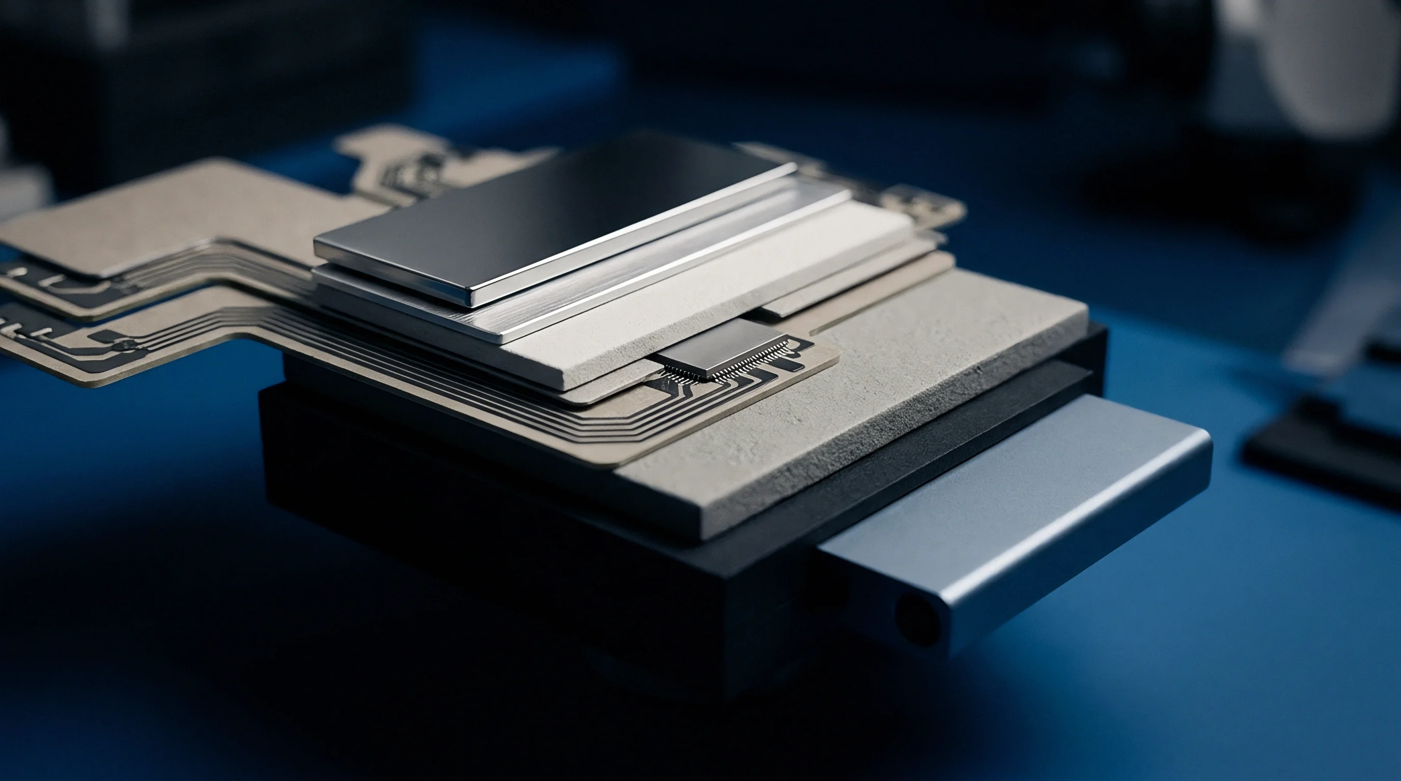
Layer thicknesses between 0.5 and 1.5 micrometers balance mechanical stress against thermal budget constraints. Thicker polysilicon films retain higher effective trap densities through full transceiver manufacturing sequences, preserving RF linearity into multi-gigahertz frequencies.
| Layer Parameter | Standard High-Resistivity | Thin Poly Trap-Rich (0.5 µm) | Optimized Poly Trap-Rich (1.5 µm) | Argon Implanted Layer |
|---|---|---|---|---|
| Interface Trap Density (eV⁻¹ cm⁻²) | 1.2 × 10¹⁰ | 4.5 × 10¹² | 1.8 × 10¹³ | 8.0 × 10¹¹ |
| Effective Resistivity at 2.4 GHz (Ω·cm) | 40 | 1200 | 3800 | 650 |
| Second Harmonic Generation at +25 dBm (dBc) | -58 | -78 | -88 | -68 |
| Thermal Stability Ceiling (°C) | 1100 | 1050 | 1000 | 450 |
| Sheet Resistance (kΩ/sq) | 2.5 | 250 | 1200 | 45 |
Unexpected high-frequency insertion loss spikes occur when thermal drive-in steps exceed the agreed thermal budget window for trap-rich wafer substrates.

Distortion
Non Linear Dynamic Capacitance in RF Power Nodes
Nonlinear voltage-dependent capacitance at the oxide-silicon interface generates strong harmonic tones in transceivers operating near peak output power. As high-amplitude RF signals travel along transmission lines or through integrated switches, the signal potential modulates the accumulation layer depth. This changing depletion width produces a dynamic voltage-dependent capacitance curve, C(V).
This dynamic capacitance acts like a nonlinear varactor diode in the RF signal path. Above +20 dBm, it generates second-harmonic (HD2) and third-harmonic (HD3) spurs, as well as third-order intermodulation distortion (IMD3) products. In sub-6 GHz 5G and Wi-Fi 6 transceivers, these harmonics fall into adjacent receive bands, desensitizing internal receivers and violating spectral emission standards.
Second harmonic distortion exceeds minus eighty-five decibels relative to carrier when trap rich layer thickness equals one point five micrometers at two point four gigahertz.
A stable trap-rich layer flattens the C(V) profile by pinning the interface potential. This prevents carrier density modulation during large signal swings, holding the capacitive load steady across the full operating voltage range.
| Frequency Band | Substrate Configuration | Insertion Loss (dB/mm) | HD2 Suppression (dBc) | HD3 Suppression (dBc) | EVM Floor (%) |
|---|---|---|---|---|---|
| 2.4 GHz Wi-Fi 6 | Standard HR-Si | 0.35 | -55 | -62 | -32 |
| 2.4 GHz Wi-Fi 6 | Trap-Rich HR-SOI | 0.08 | -89 | -94 | -45 |
| 5.8 GHz WLAN | Standard HR-Si | 0.62 | -48 | -56 | -28 |
| 5.8 GHz WLAN | Trap-Rich HR-SOI | 0.14 | -84 | -90 | -43 |
| 28 GHz mmWave | Standard HR-Si | 1.45 | -40 | -48 | -22 |
| 28 GHz mmWave | Trap-Rich HR-SOI | 0.38 | -76 | -82 | -38 |
Selection Rules for High Linearity Radio Interfaces
Front-end design choices determine how strictly surface conduction must be suppressed based on transmit power envelopes and overall link margin allocations.
- High Power Output Nodes operating above +25 dBm require a trap-rich film at least 1.0 micrometer thick to suppress nonlinear voltage harmonics.
- Wideband OFDM Modulation schemes need substrate effective capacitance variation under 0.01 femtofarads per volt to keep error vector magnitude floors below minus forty decibels.
- Multi-Band Coexistence Specs demand third-order intermodulation distortion suppression better than minus eighty-five decibels relative to carrier to protect active receive channels.
- Millimeter-Wave Front Ends require low surface roughness at the polysilicon-dielectric boundary to limit scattering loss above twenty gigahertz.
Without effective surface mitigation, front-end linearity degrades sharply under high signal levels.
Interface trap density sets the hard linearity limits for high-power RF switches and transceiver front-ends across cellular and short-range wireless standards.
Isolation
Deep Trench Isolation and Guard Ring Layouts
Deep trench barriers etched through the thin device film and buried dielectric reach directly into the bulk substrate. These Deep Trench Isolation (DTI) structures physically break up the active silicon, replacing conductive semiconductor regions with silicon dioxide or sub-micron air gaps. Surrounded by p-type contact rings tied to clean RF grounds, the trenches block lateral surface currents between adjacent circuit blocks.
Installing dual guard rings around power amplifiers prevents high-level RF currents from modulating the body potential of sensitive low-noise amplifier transistors on the same die.
- Etch narrow trenches through the front-side silicon and buried dielectric, extending at least two micrometers into the high-resistivity substrate.
- Deposit thermal oxide liners along trench sidewalls to prevent surface state generation on exposed silicon crystal faces.
- Fill the trenches with undoped polysilicon or CVD dielectric to planarize the wafer surface for subsequent metal interconnect steps.
- Form dense p-type diffusion contact rings around active RF blocks to establish low-impedance grounding into the bulk substrate.
- Remove bulk substrate material beneath high-frequency spiral inductors using localized back-side dry etching.
Localized back-side etching forms suspended dielectric membranes or open air cavities beneath critical passives, eliminating substrate dielectric and conduction loss entirely.
Integrating back-side cavity etching into high-volume QFN packaging lines remains contentious due to mechanical fragility risks during molding.

Yield
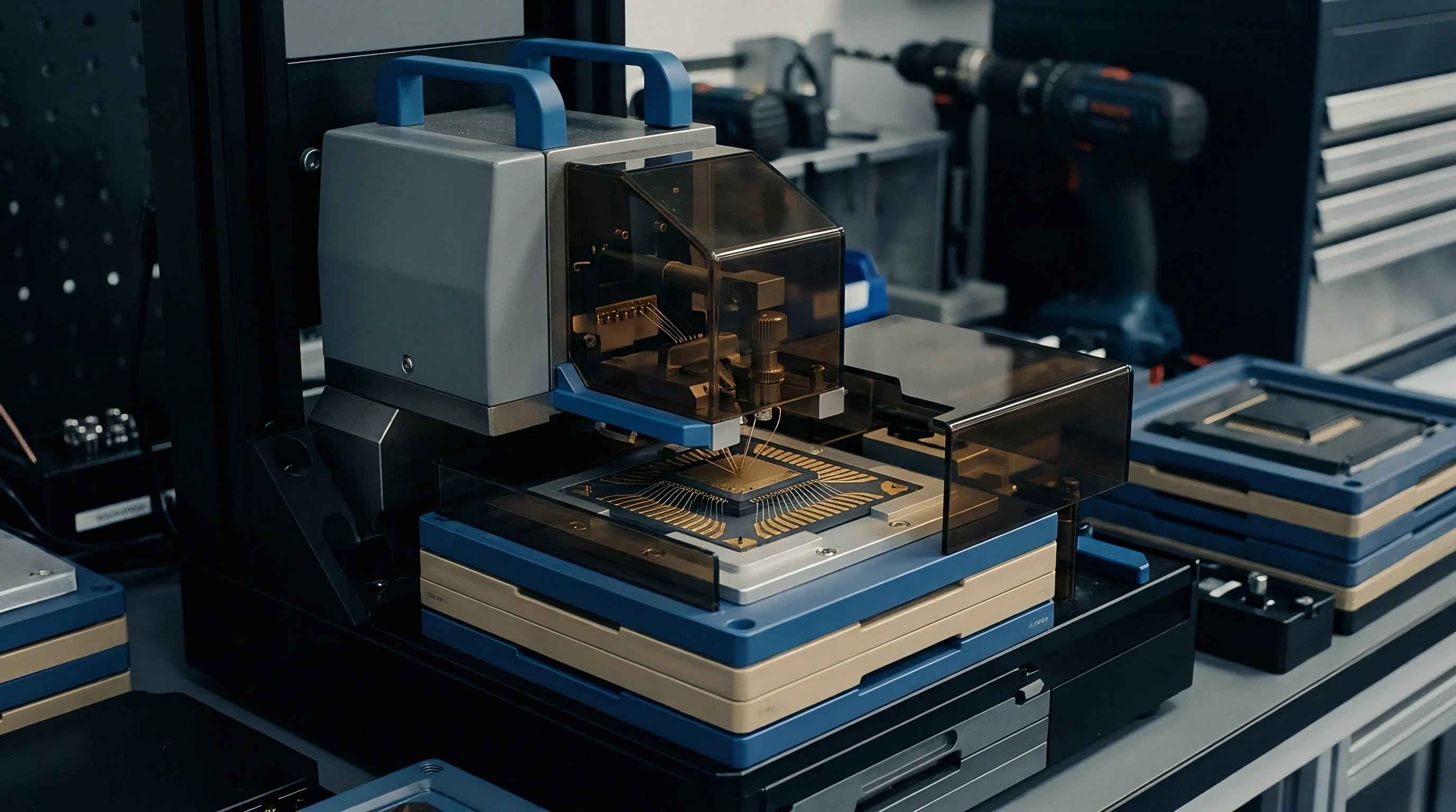
Sourcing Specifications and Thermal Donor Activation
Engineered trap-rich substrates alter wafer economics compared to standard float-zone silicon. Float-zone wafers provide high purity and initial resistivities above 5000 ohm-centimeters, but they warp easily during high-temperature processing. Advanced Czochralski high-resistivity silicon offers better mechanical strength, though it introduces interstitial oxygen into the lattice.
During thermal steps between 400 and 500 degrees Celsius, interstitial oxygen aggregates into active thermal donors. These donors release free electrons into the substrate, converting high-resistivity p-type silicon into low-resistivity n-type material.
High resistivity substrate wafers without polysilicon trap layers lose sixty percent of effective resistivity after ten hours at four hundred fifty degrees Celsius.
Foundries cap cumulative thermal budgets to mitigate this effect. Specifying low-oxygen high-resistivity substrates suppresses thermal donor formation, keeping bulk resistivity stable across transceiver manufacturing runs.
| Substrate Architecture | Raw Wafer Cost Adder (%) | RF Linearity Degradation Risk | Thermal Budget Sensitivity | Dominant Wafer Defect Mode |
|---|---|---|---|---|
| Standard Float-Zone HR-Si | Baseline (0%) | Severe (High C(V) non-linearity) | Low thermal donor risk | Wafer slip and thermal warp |
| Low-Oxygen HR-CZ Silicon | +12% | Severe without trap layer | Moderate donor activation | Oxygen precipitate formation |
| Polysilicon Trap-Rich HR-SOI | +28% | Extremely low (-88 dBc HD2) | High (Grain growth ceiling) | Trap-layer poly defect voids |
| Cavity-Etched Localized MEMS | +65% | Eliminated under passive nodes | Low | Membrane structural cracking |
Engineered trap-rich substrates increase initial wafer costs, while back-side cavity etching adds manufacturing complexity.
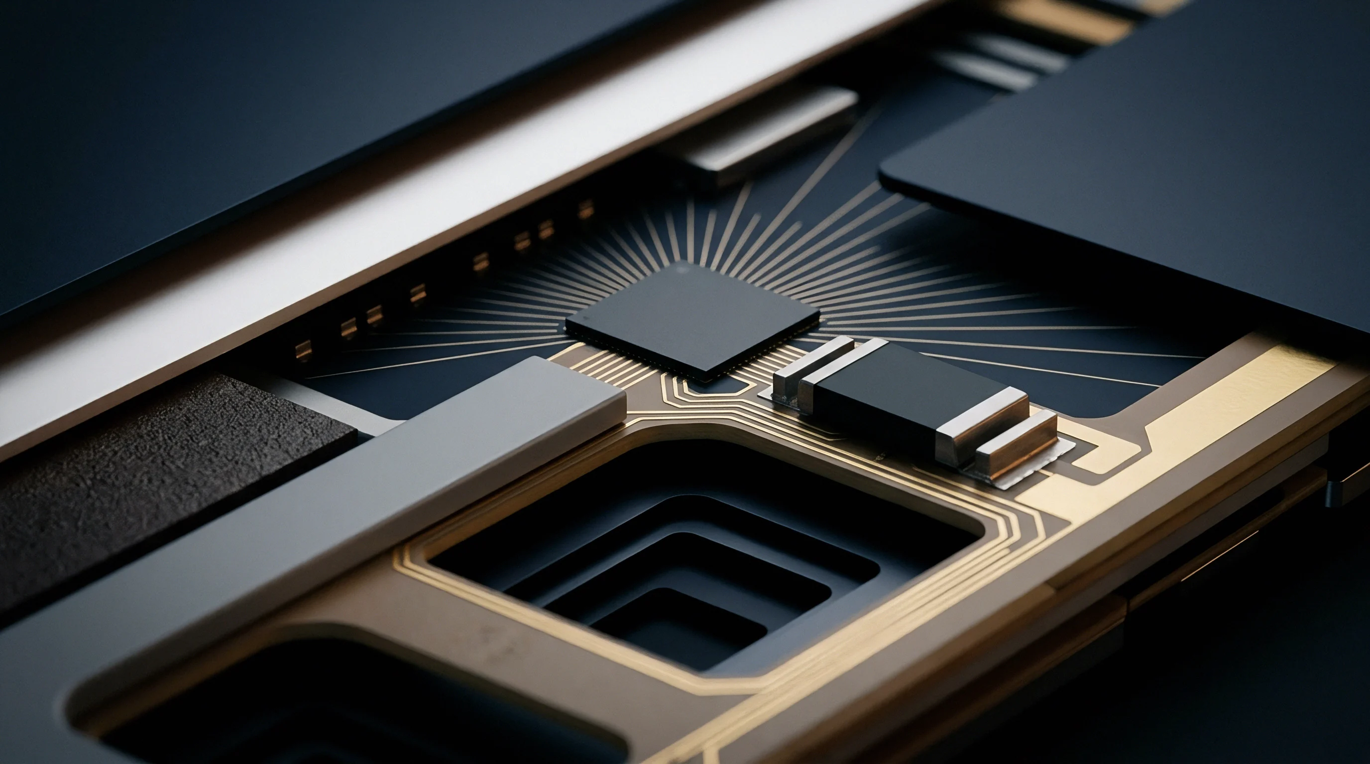
Sourcing Qualification Dossier Verification
Master supply agreements for high-resistivity RF transceiver wafers rely on strict physical and electrical qualification metrics.
- Buried Interface Trap Lifetime Audits verify carrier recombination rates using non-contact microwave photoconductive decay on post-anneal test wafers.
- Post-Fabrication RF Linearity Probing measures second- and third-harmonic levels on dedicated test structures along wafer edges.
- Interstitial Oxygen Concentration Limits cap oxygen content below 5 times 10 to the 17th power atoms per cubic centimeter using FTIR spectroscopy.
- Sheet Resistance Thermal Stability Certificates confirm sheet resistance stability after eight hours at four hundred fifty degrees Celsius.
Supply contracts require compliance with SEMI M1 substrate standards and enforce a maximum second-harmonic distortion limit of minus eighty-five decibels relative to carrier at twenty-five decibels milliwatt RF input power and two point four gigahertz across all delivered lots.