Trap Rich Layer Physics for RF Silicon Substrates
Trap-rich polysilicon layers beneath buried oxide pin interface carriers to eliminate parasitic conduction and lower sub-6 GHz harmonic generation.
Strata
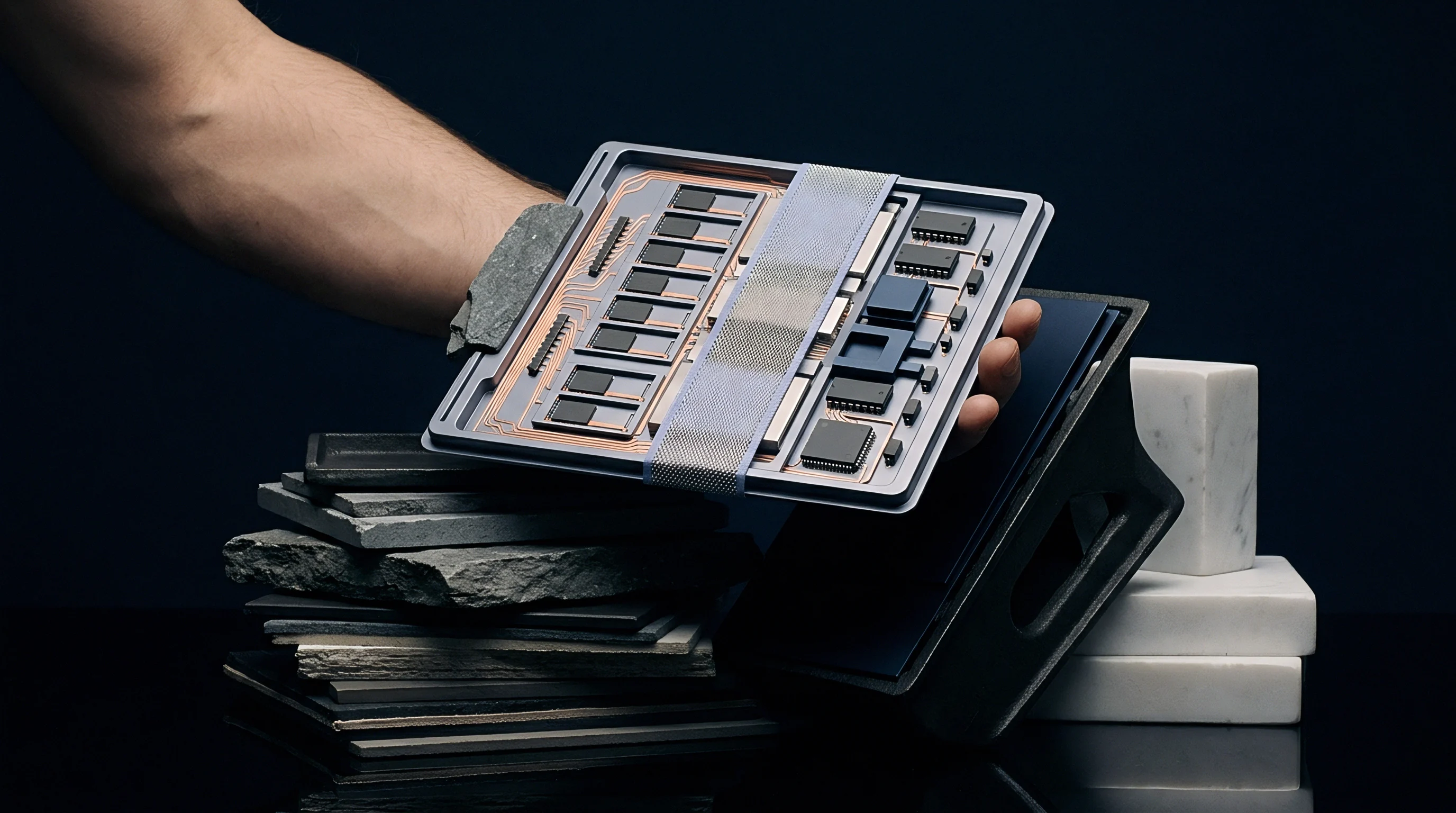
High-resistivity silicon wafers serve as the physical substrate for integrated radio frequency silicon-on-insulator devices, with standard base substrates using bulk resistivity values from 1000 ohm-centimeters to over 10000 ohm-centimeters. While high bulk resistance limits eddy current losses and capacitive coupling from active microstrip lines into the handle wafer, bulk resistivity by itself cannot protect RF signal integrity once dielectric isolation layers interface with the handle.
Buried Oxide Interfacial Physics
Thermal oxidation during wafer fabrication leaves positive fixed charges embedded within the dielectric layer, giving buried oxide isolation layers a net positive fixed oxide charge density between 10 to the 11th power and 10 to the 12th power per square centimeter. These positive ions inside the silicon dioxide pull free majority carriers out of the bulk substrate toward the handle surface, where free electrons gather at the oxide interface to form a thin, highly conductive accumulation channel.
This parasitic surface conduction ruins signal linearity. As the thin, high-density accumulation channel forms, localized sheet resistance drops below 100 ohms per square, overriding the native 3000 ohm-centimeter bulk resistance and creating a conductive path directly beneath the buried oxide. High-frequency signals passing through active switches or low-noise amplifiers couple through the oxide into this layer, resulting in heavy insertion loss, cross-talk across adjacent RF paths, and unwanted thermal power dissipation.
The accumulation of mobile electrons under dielectric interfaces creates a conductive channel that degrades signal power across high-frequency transmission structures.
Interfacial accumulation also degrades RF isolation as the thickness of the accumulation channel fluctuates dynamically under applied RF voltage swings. This applied voltage modulates the localized free carrier density beneath the buried oxide, creating a voltage-dependent junction capacitance whose interaction with the surface resistance drives strong non-linear responses. Without surface modification, RF front-end components built on high-resistivity silicon generate elevated second and third harmonic emissions that fail regulatory spectral masks.
- Fixed Oxide Charge Accumulation occurs during high-temperature thermal oxidation routines, embedding immobile positive ions near the lower oxide interface.
- Parasitic Surface Conduction Channeling arises when free electrons concentrate at the handle wafer surface, lowering localized sheet resistance by orders of magnitude.
- Voltage Dependent Capacitance Modulation develops as high-amplitude RF voltage swings expand and contract the localized electron accumulation layer thickness.
- Capacitive Substrate Signal Coupling forces high-frequency energy down through the oxide dielectric directly into the conductive interfacial boundary layer.
Fixed oxide charge variations remain an inherent outcome of standard thermal oxide growth routines.
Grain
Depositing a microscopic defect matrix directly beneath the buried oxide alters interfacial electrostatics. By integrating an undoped polysilicon or amorphous silicon layer ~ ranging from 0.3 micrometers to 1.5 micrometers thick ~ between the high-resistivity handle wafer and the buried oxide, the substrate gains a network of densely packed crystallites separated by disordered grain boundary regions whose traps lock mobile carriers.
Fermi Level Pinning and Trap Density
Microscopic grain boundaries contain dangling silicon bonds and structural atomic lattice dislocations that introduce an exceptionally high density of mid-gap electronic energy states into the silicon bandgap. Effective mid-gap trap state density exceeds 10 to the 12th power states per square centimeter per electron-volt, allowing these states to readily capture free electrons pulled in by positive fixed charges inside the buried oxide layer.
Once captured, electrons stay trapped in localized potential wells along the grain boundaries, pinning the surface Fermi level near the middle of the energy bandgap. This Fermi level pinning prevents an electron accumulation layer from forming even under strong electrostatic fields from fixed oxide charges. Mobile carrier density at the interface drops to near-intrinsic levels, driving effective surface resistance above 100000 ohms per square under both direct-current and radio-frequency bias conditions.
Mid-gap trap densities exceeding one trillion states per square centimeter prevent electron accumulation by pinning the surface Fermi level.
Recombination lifetimes fall sharply inside this trap-rich matrix. Free carriers injected into the layer during high-power RF voltage peaks recombine within picoseconds through Shockley-Read-Hall channels, suppressing charge storage during rapid voltage transients and absorbing mobile charge vectors before a coherent conductive sheet can form across the surface.
Higher grain boundary density yields cleaner signal isolation across elevated operational temperatures.

Distortion
Radio frequency switches operating in fifth-generation mobile networks require extreme signal linearity across elevated power levels. Transmit circuits driving signals into antenna matching networks generate peak voltage swings exceeding 30 volts across active switch nodes. Non-linear substrate parasitics convert fundamental signal energy into unwanted harmonic frequencies and intermodulation products.
Harmonic Generation and Intermodulation Mechanics
Substrate non-linearity stems from the voltage dependency of the substrate-to-oxide capacitance. On standard high-resistivity substrates, capacitance varies non-linearly with applied voltage as the surface accumulation layer shifts under high drive power, producing second-harmonic and third-harmonic output terms whose amplitudes scale with input power levels.
Integrating a trap-rich layer stabilizes substrate capacitance across the entire operational voltage envelope. Pinning the interface charge renders the substrate capacitance nearly constant with respect to instantaneous RF voltage swings, bringing the differential capacitance derivative close to zero across broad voltage ranges. Second-harmonic distortion decreases by more than 25 decibels compared to standard high-resistivity silicon under identical driving power conditions.
Integrating high-density surface traps depresses second-harmonic emissions below minus ninety decibels relative to the fundamental carrier at thirty watt power levels.
Cross-modulation distortion also collapses inside trap-rich architectures. In multi-band cellular architectures, high-power transmissions in lower frequency bands modulate the phase and amplitude of sensitive low-power signals in upper frequency bands through shared substrate capacitance. Trap-rich layers attenuate cross-talk coupling by maintaining high surface impedance across all operational bands spanning 400 megahertz to 7125 megahertz.
| Substrate Architecture | Surface Sheet Resistance (ohms/sq) | CPW Loss at 5.8 GHz (dB/mm) | Second Harmonic HD2 (dBc) | Third Harmonic HD3 (dBc) |
|---|---|---|---|---|
| Standard High-Resistivity Silicon (1000 ohm-cm) | 80 | 0.75 | -62 | -58 |
| High-Resistivity Silicon (5000 ohm-cm, No Trap Layer) | 120 | 0.42 | -68 | -63 |
| Standard Trap-Rich HR-SOI (0.5 um Polysilicon) | 150000 | 0.08 | -88 | -84 |
| High-Density Trap-Rich HR-SOI (1.2 um Polysilicon) | 500000 | 0.04 | -96 | -91 |
Selecting high-resistivity substrates without adequate surface trap density leads to radiated emission test failures during commercial compliance testing.
Metrology
Small-signal parameter extraction and direct current measurements fail to expose the non-linear conduction channels formed by interface charges. Four-point probe resistivity instruments measure bulk majority carrier conduction across deep substrate volumes while remaining blind to thin interfacial accumulation channels. Evaluating trap-rich efficacy requires specialized high-frequency and large-signal characterization methodologies.

Can Substrate Harmonic Distortion Be Derived from DC Resistivity Alone?
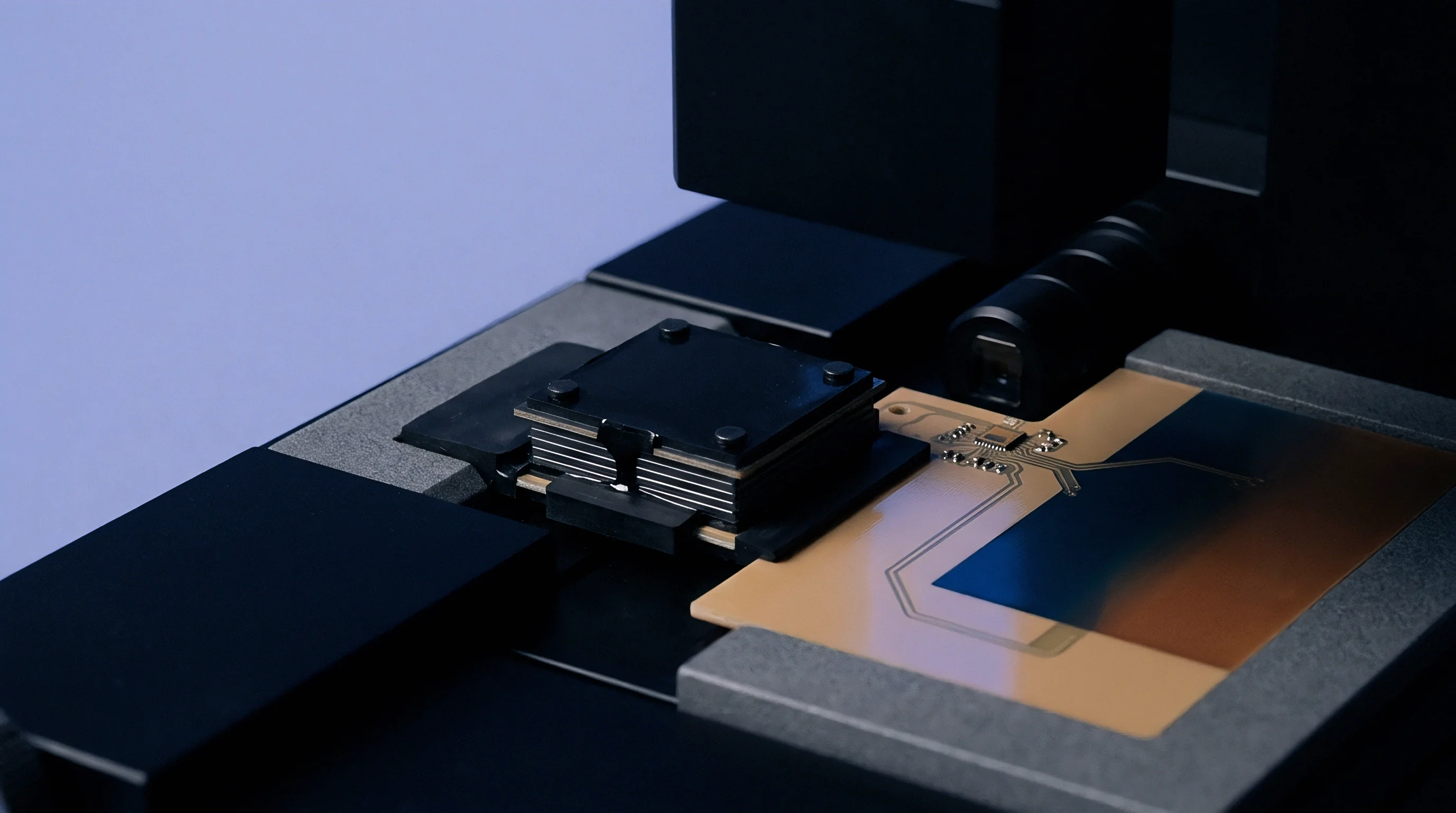
Four-point probe instruments evaluate bulk majority carrier concentration near room temperature, but interfacial accumulation layers measure less than 20 nanometers in thickness. High-frequency coplanar waveguide structures patterned directly onto un passivated substrates offer an accurate metric of surface attenuation, as RF signals propagating down coplanar waveguides couple energy directly into the interfacial boundary layer, exposing localized sheet resistance drops through attenuation measurements expressed in decibels per millimeter.
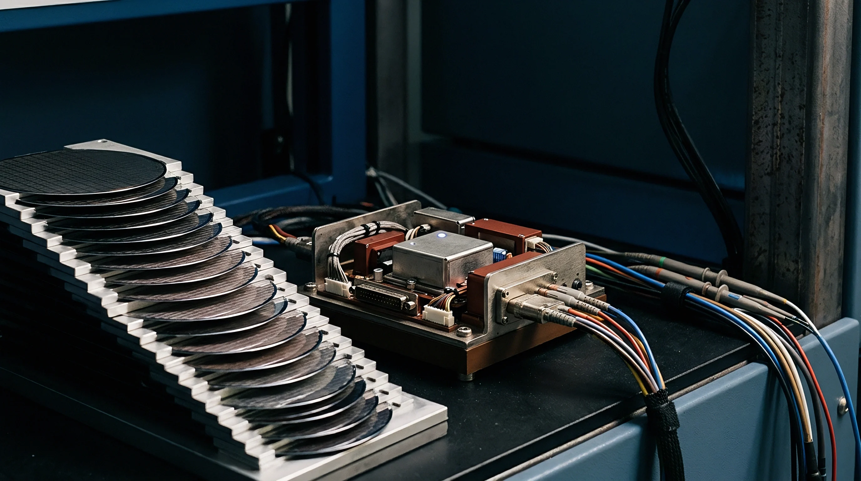
Large-signal harmonic power sweeps provide explicit proof of trap layer functionality under actual operational conditions. An RF signal generator drives a high-purity fundamental tone through a power amplifier into the device under test. Precision harmonic filters eliminate source generator harmonics prior to the substrate interface.
High-dynamic-range spectrum analyzers monitor generated harmonic power across fundamental drive levels stepping from +10 dBm to +36 dBm.
- Calibrate microwave vector network analyzer power source across sweep range from 100 megahertz to 40 gigahertz.
- Measure scattering parameters on customized coplanar waveguide test coupons fabricated over candidate substrates.
- Extract frequency-dependent attenuation constants to calculate true high-frequency surface sheet resistance values.
- Apply large-signal fundamental drive power through a low-pass filter while observing harmonic responses on a spectrum analyzer.
Thermal stress testing evaluates trap stability under elevated ambient operating environments. Wafer heating stages raise substrate temperatures to 125 degrees Celsius while measuring harmonic output power. Elevated thermal energy excites trapped electrons out of mid-gap states back into the conduction band, meaning effective trap layers must retain sufficient trap density at high temperatures to preserve surface impedance margins.
Whether high-frequency capacitance voltage extraction can completely replace physical harmonic power sweeps on wafer lines remains undetermined.
Slab
Depositing a trap-rich layer demands tight control over chemical vapor deposition parameters. Low-Pressure Chemical Vapor Deposition process conditions dictate the initial grain structure, crystallite orientation, and trap density of the polysilicon layer. Deposition temperatures maintained between 580 degrees Celsius and 620 degrees Celsius yield fine-grained microcrystalline films with optimal defect concentrations, whereas deposition above 630 degrees Celsius promotes large crystal grain formation that reduces total grain boundary area and lowers overall trap state density.
Thermal Budget and Grain Recrystallization
Downstream CMOS process routines expose substrates to substantial thermal budgets. Gate oxide growth, dopant activation annealing, and chemical vapor deposition cycles subject wafers to temperatures ranging from 900 degrees Celsius to 1050 degrees Celsius. Thermal annealing drives grain growth inside the polysilicon film, causing small crystallites to coalesce into larger grains and lowering the total volume of grain boundaries.
Thermal stress during annealing alters grain boundaries and annihilates carrier traps. If prolonged high-temperature exposure drops mid-gap trap density below 5 times 10 to the 11th power states per square centimeter, mobile electrons re-accumulate beneath the buried oxide layer. Device foundries mitigate grain growth by co-doping the polysilicon matrix with trace concentrations of interstitial oxygen or nitrogen atoms during deposition, pinning grain boundaries to prevent structural recrystallization during subsequent high-temperature anneals.
Wafer processing thermal budgets above one thousand degrees Celsius induce grain growth that reduces grain boundary density and degrades surface trapping efficacy.
- Thermal Grain Growth Recrystallization expands average polysilicon crystal dimensions while eliminating microscopic defect sites along grain boundaries.
- Interstitial Atom Dissolution reduces the pinning force on grain boundaries when thermal budgets exceed established duration limits.
- Trap State Annihilation reduces mid-gap energy state counts below the threshold necessary to pin interfacial free electrons.
- Amorphous Phase Transition Shift transforms metastable non-crystalline silicon structures into relaxed polycrystalline forms with lower internal trap states.
Standard wafer procurement contracts specify post-anneal second-harmonic limits below minus eighty-five decibels relative to carrier under thirty-three decibels milliwatt excitation.
Acceptance
Wafer procurement specifications for high-performance front-end modules require clear boundary metrics for radio frequency linearity. Sourcing high-resistivity silicon-on-insulator wafers carrying certified trap-rich layers adds a cost premium between 15 percent and 25 percent over base high-resistivity wafers. Sourcing teams balance substrate cost against end-product yield losses caused by harmonic emission non-compliance.
Quality Qualification and Sourcing Parameters
Substrate qualification relies on standardized test structures integrated into wafer scribe lines or dedicated test wafers per manufacturing lot. Certificates of analysis accompany incoming wafer lots, documenting bulk handle resistivity, buried oxide thickness, polysilicon layer thickness, and post-anneal coplanar waveguide attenuation rates. Failure to verify trap stability post-annealing introduces severe compliance risks for finished packaged front-end modules.
| Parameter Specification | Standard High-Resistivity SOI | Qualified Trap-Rich HR-SOI | Test Condition / Standard Reference |
|---|---|---|---|
| Handle Bulk Resistivity | 1000 ohm-cm | 3000 ohm-cm | SRP Profiling at 25 degrees Celsius |
| Buried Oxide Thickness | 140 nm to 400 nm | 200 nm to 400 nm | Spectroscopic Ellipsometry Metrology |
| Polysilicon Trap Layer Thickness | 0.0 um (Absent) | 0.3 um to 1.0 um | Cross-Sectional TEM Imaging |
| Surface Sheet Resistance | 100000 ohms/sq | High-Frequency CPW Extraction at 2.4 GHz | |
| Max 2nd Harmonic Emission (HD2) | -65 dBc | +33 dBm Drive at 1.9 GHz Fundamental | |
| CPW Attenuation Rate | 0.60 dB/mm | On-Wafer RF Probing up to 20 GHz |
Module designers targeting multi-mode WiFi 7 and 5G sub-6 GHz systems mandate certified trap-rich substrates across all high-power switch nodes, where RF losses scale with frequency and switching ICs require linear substrates. Substrates failing second-harmonic verification under full-power driving conditions force costly product re-spins and delay commercial regulatory approvals, making lot acceptance testing essential to confirm that qualified trap-rich substrates maintain harmonic margins through final packaging and assembly steps.