Quantifying Near-Field Common-Mode Coupling and Dynamic Intermodulation in Dense Transceiver Enclosures
Dense transceiver enclosures generate common-mode currents and dynamic intermodulation across metal seams, requiring early near-field scanning to prevent costly compliance retests.


Leak
Packing multiple transceivers, high-speed digital buses, and switching power converters into compact aluminum or copper enclosures creates severe layout compromises. When differential traces cross splits in a reference plane or pass close to housing seams, asymmetric electric fields induce common-mode voltages directly on the main PCB ground plane. These RF voltages drive return currents through the internal chassis, flexible flat cables, and external I/O shields.
In enclosures under one hundred millimeters across, inductive and capacitive coupling between adjacent front-ends degrades receiver noise floors well before any distortion appears on differential lines.
Inside tight metal cavities, coupling is governed by reactive near-field interactions rather than far-field plane waves. The magnetic near-field dominates out to the boundary of the wavelength divided by two pi ~ roughly twenty millimeters from a radiating trace or aperture at 2.4 GHz. Traces carrying steep di/dt edges induce surface currents on nearby metal shields through mutual inductance.
If an enclosure seam approaches a significant fraction of the operating wavelength, shielding effectiveness drops sharply and the seam behaves like a slot antenna.
Physical proximity converts local circuit asymmetry directly into chassis-wide RF current distribution.
Electric near-field coupling stems from stray capacitance between high dv/dt nodes ~ such as switching inductors or power amplifier matching networks ~ and the surrounding enclosure walls. This capacitive link injects common-mode current directly into the housing, where it spreads along the interior metal toward the lowest-impedance return path back to the PCB. Fastener torque variations, anodized finishes, and gasket interfaces alter this path, creating localized impedance steps that steer RF energy through seams and drive attached cables as dipole radiators.
While self-contained shield cans are often treated as complete isolation barriers, near-field coupling frequently bypasses them entirely, shifting radiated emission failures onto board layout geometry and peripheral cable filtering.
Mixing
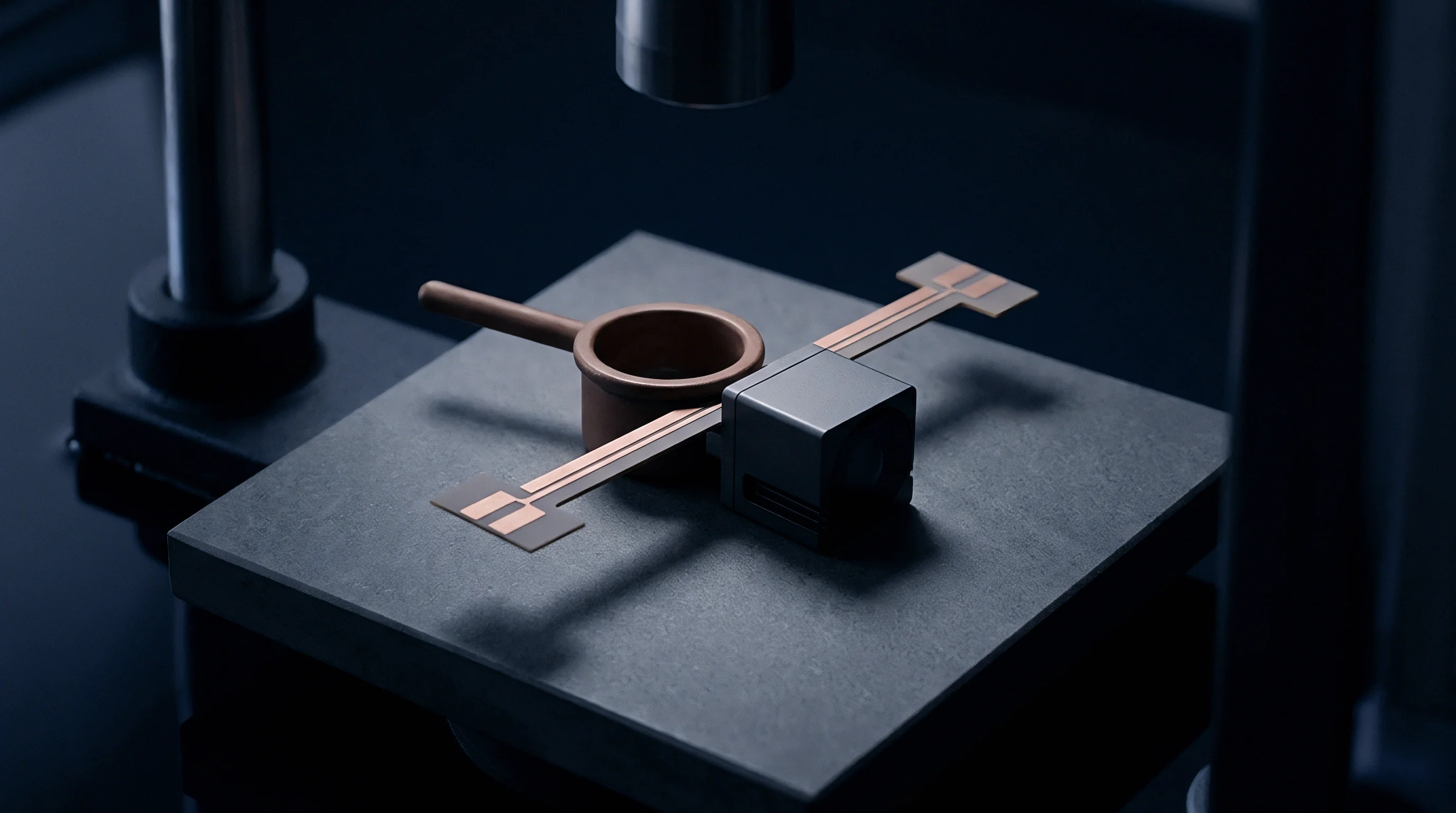
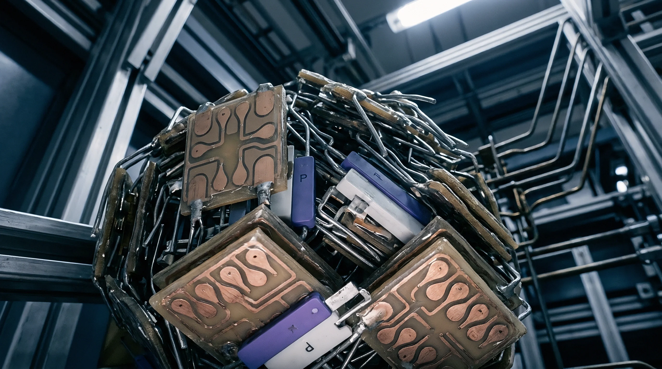
Nonlinear junctions inside dense transceiver housings generate spurious mixing products under multi-carrier conditions. When two or more strong transmit signals couple into the same mechanical structure, physical junctions can modulate the carriers and drop dynamic intermodulation products straight into sensitive receiver bands. Unlike static passive intermodulation driven by fixed material properties, dynamic intermodulation fluctuates with transmit power, operating temperature, and mechanical stress on the chassis.
Nonlinear Junction Behavior in Shielding Cavities
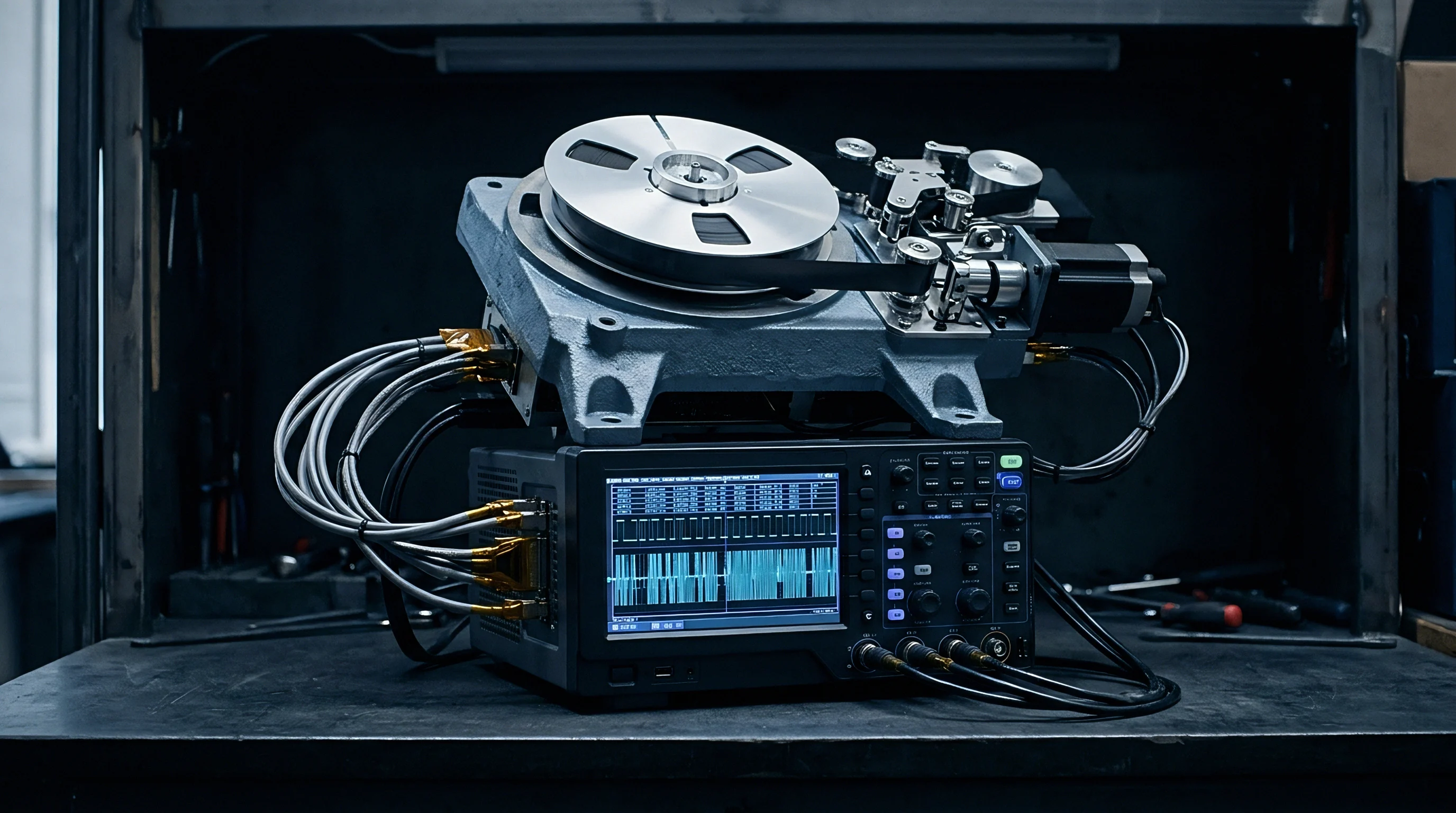
Mated metal surfaces along enclosure seams can act like metal-insulator-metal diodes under strong near-field excitation. Surface oxidation, light corrosion, or uneven clamping pressure creates a thin tunneling barrier with a voltage-dependent response. When high common-mode currents cross these compromised seams, the resulting nonlinear voltage drops generate third- and fifth-order intermodulation products.
Solid-state switches, LNA protection diodes, and ESD arrays on inactive transceivers also serve as unintended mixing nodes. Strong fundamental energy from an active transmitter conducts through chassis paths to unpowered or standby RF ports, pushing ESD diodes beyond their linear range and re-radiating mixing products back into the enclosure cavity.
A two-tone drive of 27 dBm at 2412 MHz and 2462 MHz generates a third-order intermodulation product of -82 dBm at the receiver port when cavity isolation falls below 35 dB.

Passive and Dynamic Intermodulation Mechanisms
Separating seam-generated intermodulation from active component mixing requires dedicated isolation tests during cavity characterization. Base metals, plating chemistries, and fastener spacing largely set the baseline amplitude of these spurious products.
| Seam Configuration | Contact Impedance (mΩ) | Third-Order IMD Level (dBm) | Coupling Mechanism |
|---|---|---|---|
| Bare Aluminum with Nickel Gasket | 1.2 | -112 | Galvanic Seam Tunneling |
| Clear Anodized with Stainless Screws | 45.0 | -78 | Oxide Barrier Rectification |
| Chromate Conversion with Beryllium Copper | 0.8 | -118 | Conduction Surface Loop |
| Direct Plastic-to-Metal Paint Edge | 180.0 | -64 | Capacitive Micro-Arc Junction |
Tight metal enclosures can turn passive mechanical joints into active mixers. Because the resulting spurious energy enters directly through the antenna port, digital baseband filtering cannot remove it, causing desensitization across multiple operating channels at once.
As transceivers are placed closer together, several failure mechanisms recur across multi-radio hardware:
- Galvanic Rectification Oxide layers between chassis plates rectify common-mode RF currents, broadcasting broadband harmonic noise.
- LNA Rectification Off-state receiver front-ends generate intermodulation sidebands when strong near-field transmit signals cross ESD protection diodes.
- Gasket Cavity Resonance Structural conductive elastomer gaskets lose contact at specific mechanical nodes, creating resonant slot antennas that enhance mixing product radiation.
- Power Rail Mixing Common-mode ripple on power distribution networks modulates RF power amplifier drivers, generating unwanted sidebands across adjacent frequency channels.
Pushing seam-generated intermodulation below the thermal noise floor in dense multi-gigahertz radios may eventually force a transition to monolithic single-die shielding architectures.
Ground
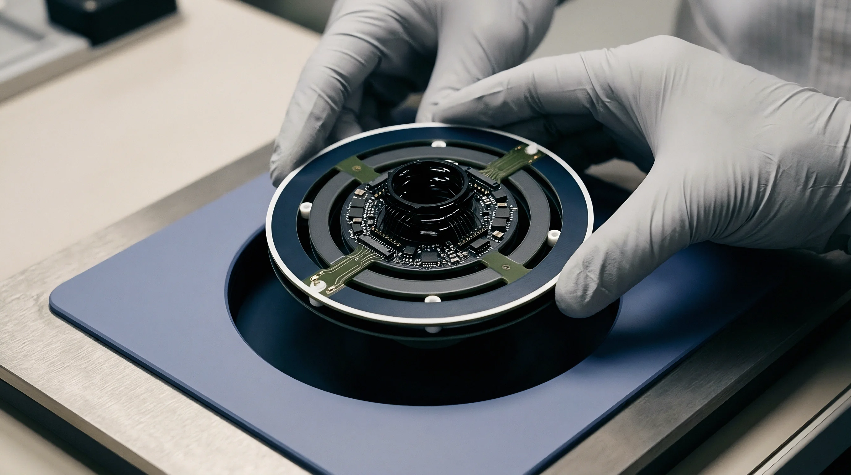
Radiated emission standards restrict equipment emissions by imposing ceilings on allowable common-mode current and field intensity. ETSI EN 301 489-1 and CISPR 32 specify strict radiated limits for information technology and radio hardware in commercial and industrial settings. As little as five microamperes of common-mode current on an external cable can exceed Class B limits at a ten-meter test distance, making ground continuity across every seam and connector interface critical to compliance.
Which Regulatory Clauses Govern Common Mode Radiation from Metallic Enclosures?
Unintentional radiators fall under FCC Part 15 subpart B, which establishes field strength limits from 30 MHz up to 40 GHz and beyond. Clause 15.109 sets limits for radiated emissions and assigns host integrators full responsibility for aperture leakage from metallic enclosures. For intentional transmitters under subpart C or E, clause 15.209 dictates limits in restricted bands; intermodulation leakage escaping through chassis seams can void existing modular approvals and force complete host-level recertification.
The European Union regulates these products under the Radio Equipment Directive 2014/53/EU. ETSI EN 300 328 and EN 300 440 set spurious emission limits down to -30 dBm in active bands and -54 dBm in standby states. Common-mode mixing across transmitters routinely breaches these levels during standard turntable sweeps inside anechoic chambers.
Compliance documentation for multi-transceiver hosts must explicitly list common-mode noise suppression measures whenever integrated radio modules share a common metallic frame.
Common Mode Current Thresholds and Compliance Boundaries
Avoiding test-lab failures requires thorough prototype-stage qualification. Integrators evaluate ground continuity, stackup transitions, and filter performance through systematic bench checks:
- Verify reference plane continuity across board stackups, eliminating ground splits beneath high-speed differential pairs and RF feeds.
- Measure common-mode current levels on all cable assemblies using a calibrated current probe before placing the unit inside the test chamber.
- Inspect mechanical seam tolerances, confirming gasket compression exceeds thirty percent along the entire mating perimeter.
- Evaluate spurious emission spectrum outputs under simultaneous multi-transceiver transmission modes to capture dynamic intermodulation spikes.
- Document host enclosure attenuation figures to support Class II permissive change filings under FCC and ISED rules.
Under FCC KDB 996369 D04, host integrators are legally accountable for emissions caused by near-field intermodulation and common-mode leakage, regardless of whether the installed radio modules were previously certified independently.
Bench
Measuring near-field common-mode coupling requires bench instruments that separate electric and magnetic field components. While far-field chamber testing shows whether a device passes or fails, it cannot pinpoint the responsible seam, trace, or nonlinear junction. Miniature shielded loops and electric field monopole probes map local field gradients across board surfaces and interior metal walls, isolating current loops and capacitive injection points with sub-millimeter resolution.

Near Field Probe Calibration and Spatial Scanning
Probe calibration relies on measuring complex transfer impedance across the target frequency span. Running the probe over a microstrip fixture with a known field profile yields the correction factors needed to convert spectrum analyzer voltage into absolute magnetic field (A/m) or electric field (V/m) values.
Motorized three-axis gantries traverse the active board assembly in steps smaller than the narrowest conductor. Software matches probe coordinates with spectral sweeps, generating spatial field plots that highlight where internal RF energy couples into housing seams and chassis return paths.

Dynamic Intermodulation Extraction Protocol
Accurate dynamic intermodulation characterization requires a two-tone test setup that avoids intermodulation inside the signal sources. Separate power amplifiers drive two frequencies into distinct transmit paths within the enclosure. High-isolation directional couplers and notch filters block reverse coupling between signal generators, ensuring that observed intermodulation originates entirely within the device under test.
Consider a dual-transceiver system operating inside a cast aluminum enclosure. Transceiver A transmits at f1 = 2412 MHz with a power output of +24 dBm. Transceiver B transmits at f2 = 2462 MHz at +20 dBm.
Near-field magnetic coupling across a shared chassis ground trace exhibits a transfer coefficient of S21 = -28 dB at 2.4 GHz. The common-mode voltage induced on the chassis loop is calculated as follows:
V_cm = sqrt(P_transmit 50) 10^(S21 / 20)
For Transceiver A, the RMS voltage across 50 ohms equals 3.55 volts. Applying the -28 dB transfer coefficient yields a common-mode voltage of 0.141 volts (141 mV) driving the chassis ground loop. This common-mode voltage induces a common-mode current on an unshielded peripheral cable with an antenna input impedance of 150 ohms:
I_cm = V_cm / Z_cable = 0.141 / 150 = 0.94 mA (940 uA)
A common-mode current of 940 microamperes radiating from a one-meter cable produces a electric field strength exceeding 1,200 microvolts per meter at three meters distance. The FCC Class B limit line at three meters is 100 microvolts per meter (40 dBuV/m). Near-field common-mode coupling in this dense enclosure exceeds the regulatory threshold by more than 21 dB.
| Uncertainty Contributor | Probability Distribution | Standard Uncertainty (dB) | Sensitivity Coefficient |
|---|---|---|---|
| Near-Field Probe Factor Calibration | Normal (k=2) | 0.45 | 1.0 |
| Gantry Positional Accuracy (x-y-z) | Rectangular | 0.25 | 0.8 |
| Spectrum Analyzer Absolute Amplitude | Normal (k=2) | 0.50 | 1.0 |
| RF Cable Phase and Amplitude Drift | U-Shaped | 0.15 | 1.0 |
| Enclosure Temperature Variation | Rectangular | 0.30 | 0.5 |
Rigorous test discipline prevents measurement artifacts during debugging. The following setup checks help maintain repeatability across test runs:
- Probe Grounding Verify probe coaxial shields feature ferrite suppression sleeves to block shield current feedback into the spectrum analyzer.
- Preamplifier Linearity Confirm external low-noise preamplifiers operate at least 15 dB below their 1 dB compression point during multi-tone scanning.
- Fixture Isolation Ensure the test fixture isolation exceeds the target intermodulation dynamic range by at least 10 dB across all test frequencies.
- Cable Placement Clamp test interface cables in fixed positions to prevent geometry-induced common-mode impedance changes between sweep cycles.
Ground plane currents always seek the path of minimum transfer impedance rather than minimum physical resistance.

Docket
Emissions failures caused by near-field intermodulation can stall commercial rollouts and trigger substantial re-engineering costs. Anechoic chamber time runs from $300 to $600 per hour, separate from redesign overhead. Correcting a failure typically delays market introduction by four to twelve weeks while engineering teams spin board revisions, evaluate conductive gaskets, or modify enclosure tooling.
Permissive Changes and Multi Transmitter Module Integration
Modular certifications do not guarantee end-product compliance once modules are integrated into a shared chassis. Under 47 CFR Section 2.1043, the FCC requires a Class II permissive change when enclosure coupling alters emissions or antenna behavior. If near-field interactions between two certified modules produce unapproved intermodulation sidebands, the modular grant no longer applies, requiring new SAR and radiated spurious test data under a formal Class II filing.
European market entry requires similar reassessment under ETSI EG 203 367 for combined radio equipment. The host manufacturer holds full legal responsibility under the RED; if dynamic intermodulation produces out-of-band spurious emissions that exceed harmonized limits, customs authorities can block shipments at the border.
Unplanned enclosure re-engineering triggered by dynamic intermodulation adds an average of $85,000 in chamber fees and local representation expenses per market filing.

Regulatory Retest Costs and Launch Schedule Impact
Global launches demand parallel submissions to regional authorities, each with separate test sample counts, administrative costs, and local representative requirements. Coupling problems caught late in compliance testing multiply expenses across every target jurisdiction simultaneously.
| Target Market | Regulatory Authority | Filing Category | Typical Lead Time (Weeks) | Retest Expense Range (USD) |
|---|---|---|---|---|
| United States | FCC | Class II Permissive Change | 4 to 6 | $12,000 to $28,000 |
| European Union | Notified Body (RED) | Type Examination Certificate | 3 to 5 | $15,000 to $35,000 |
| China | SRRC | Full Radio Type Approval | 8 to 12 | $22,000 to $48,000 |
| Japan | MIC / Giteki | Category Modification | 4 to 7 | $10,000 to $24,000 |
Treating common-mode near-field interactions as an afterthought in enclosure design consistently leads to compliance failures, unplanned chamber expenses, and slipped product launches.