Trace Layout and RF Exposure Verification in Modular Host Certification
Verify host RF trace layout tolerances, calculate multi-radio exposure exclusions, and run radiated chamber spot checks to validate modular radio grants.

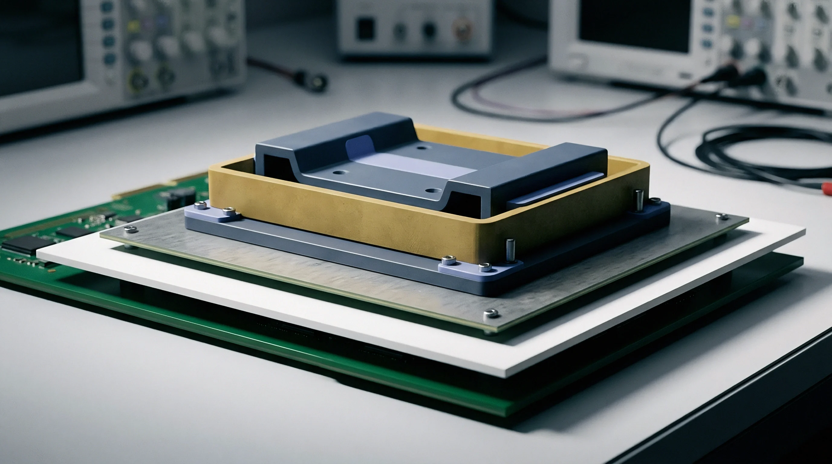
Etch
A certified modular radio transfers its FCC grant and ISED certificate to a host board only while the host antenna trace follows the exact geometry, stackup, and passive component values authorized in the module integration instructions. Deviations in trace width, dielectric height, substrate material, or component placement alter characteristic impedance, elevate voltage standing wave ratio (VSWR), and generate radiated spurious emissions across harmonic passbands. FCC KDB 996369 D02 and D04 govern these trace design layouts, defining the boundary where host design preserves the original grant or forces a Class II Permissive Change (C2PC).
Controlled impedance microstrip, stripline, and coplanar waveguide with ground (CPWG) topologies demand continuous return paths directly beneath the RF line. A break in the reference ground plane beneath an antenna feedline creates an inductive loop, converting conducted RF energy into unintended chassis radiation. Sourcing teams reviewing original equipment manufacturer (OEM) board spins verify that the radio frequency trace conforms to the manufacturer’s layout template down to the mil.
Production tolerances on FR4 dielectric constant variation (typically 4.2 to 4.8 across lot runs) shift the center frequency of matching networks, degrading return loss from the nominal 15 dB design floor to worse than 8 dB. That mismatch degrades total radiated power (TRP) and forces power amplifier output stages into non-linear compression.

Microstrip and Coplanar Waveguide Layout Tolerances
Trace geometry verification starts with physical board cross-sectioning and micro-measurement. Integration guidelines from radio chipmakers specify exact copper trace width, line spacing to adjacent ground pours, solder mask thickness, and substrate layer thickness. Fabricators running standard IPC Class 2 processes permit copper width tolerances of plus or minus 15 percent, a variance that shifts a nominal 50-ohm line to 44 ohms or 58 ohms on thin 4-mil prepreg layers.
Board files submitted for laboratory evaluation document the calculated characteristic impedance across every segment between the module output pin and the antenna connector.
A 10 percent deviation in host board dielectric height drops transmission line return loss below 10 dB at 5.8 GHz.
Ground via fencing prevents surface-wave excitation and cross-coupling into adjacent digital lines. Guidelines establish via spacing pitch at less than one-twentieth of the guided wavelength at the highest operating frequency. For a 5.8 GHz Wi-Fi 6 or 6 GHz Wi-Fi 6E transmitter, via pitch sits below 1.5 millimeters along the entire coplanar ground perimeter.
Omission of ground vias along the trace flank creates parasitic slot antennas that radiate at harmonic frequencies during conducted transmit bursts.

Where Does Host Trace Deviation Void the Grant?
Modular grants classify RF connection paths into two operational categories: connectorized outputs and trace-to-pin layouts. Modules utilizing integrated U.FL, MHF4, or onboard ceramic antennas carry self-contained RF paths. Modules terminating in surface-mount land grid array (LGA) or castellated pads depend entirely on the host printed circuit board to complete the antenna feedline.
The integration manual contains the approved trace design file, Gerbers, and Gerber-derived dielectric requirements.
| Layout Parameter | Design Target | Allowable Tolerance | Measurement Instrument | Non-Compliance Impact |
|---|---|---|---|---|
| Trace Width (W) | 0.30 mm (CPWG) | ±0.025 mm | Optical Microsection | Impedance shift to 44 Ω |
| Ground Gap (S) | 0.20 mm | ±0.020 mm | Optical Microsection | Increased line capacitance |
| Dielectric Height (H) | 0.10 mm (FR4) | ±10 percent | Scanning Electron Microscopy | Return loss degrades to 8 dB |
| Via Fence Pitch (P) | 1.20 mm | Maximum 1.50 mm | Coordinate Measurement | Radiated spurs rise 6 dB |
| Matching Component Tol | 0402 C/L values | ±0.1 pF / ±0.1 nH | Vector Network Analyzer | Passband detuning by 120 MHz |
Host integrators verify matching networks using calibrated vector network analyzers (VNA). The test engineer solders a semi-rigid coaxial pigtail directly to the module RF output pad on an unpopulated board, performing a Short-Open-Load-Thru (SOLT) calibration up to the third harmonic. The measured insertion loss across the trace must match the value logged in the module original test report within 0.5 dB.
A discrepancy exceeding 0.5 dB in insertion loss or a return loss worse than 10 dB across the operational band invalidates the modular grant. Unmatched host traces cause failure during radiated spurious emissions scans, resulting in board redesigns that halt product delivery schedules by twelve weeks.

Boundary
Modular certifications define strict boundaries between transmitter authorization and host-level compliance. Full modular approval under FCC Section 15.212 permits an integrator to incorporate a pre-approved radio into an end-product enclosure without repeating full intentional radiator testing. Limited modular approval (LMA) applies when a module lacks onboard power supply regulation, integrated RF shielding, or a dedicated crystal oscillator.
Under LMA conditions, the module manufacturer retains responsibility for reviewing every host implementation before the final product enters customs clearance.
Host manufacturers perform verification under the FCC Supplier Declaration of Conformity (SDoC) or certification procedures for unintentional radiator elements, governed by FCC Part 15 Subpart B. The integration of an approved radio does not exempt the host mainboard, display drivers, switched-mode power converters, or high-speed memory interfaces from electromagnetic compatibility (EMC) testing. Radiated and conducted emissions from digital circuitry routinely mix with the modular carrier frequency, generating intermodulation products that violate band-edge limits.
Grant Conditions and Integration Obligations
Every modular approval grant carries explicit notes detailing antenna gain maximums, host separation distances, and co-location constraints. An antenna substitution that increases peak gain beyond the value listed on the grant invalidates the filing. The integrator selects an antenna of the same type (such as dipole, patch, or inverted-F) with equal or lower gain than the referenced grant antenna.
Selecting a higher-gain antenna or an antenna of a different operating class triggers a Class II Permissive Change by the grant holder or a fresh certification by the host manufacturer under a new FCC ID.
- Antenna Type Equivalence establishes that replacement antennas share identical in-band radiation patterns, impedance curves, and polarization characteristics with the certified reference part.
- Shielding Integrity Checks verify that host structural cutouts, plastic seams, and display bezels do not reflect transmitter energy back into the module RF circuitry.
- Power Supply Ripple Limits dictate that host regulators supply DC rail voltages within the exact tolerance specified by the module datasheet, suppressing transient phase noise.
- Firmware Lockout Verification confirms that the host interface cannot access low-level radio registers to exceed country-specific output power limits or activate unauthorized frequencies.
FCC Section 15.212(a)(1)(ii) dictates that modular transmitters maintain internal RF and power circuitry shielding to prevent coupling with host circuitry.
ISED Canada sets equivalent host integration rules under Radio Standards Procedure RSP-100 and RSS-Gen. The host product carries an external label displaying the original transmitter certification number preceded by the terminology Contains IC. In the European Union, the Radio Equipment Directive (RED) 2014/53/EU rejects the concept of modular grant pass-through.
The final host assembly constitutes radio equipment in its entirety, requiring an updated EU Declaration of Conformity underpinned by host-level assessment against harmonized standards EN 300 328, EN 301 893, and EN 301 489-17.
FCC KDB 996369 D04 module integration guidance defines the explicit test regimes host manufacturers execute to demonstrate compliance, as detailed in Section 3.2 of the publication.


Exposure
Host product enclosures dictate whether a modular transmitter operates under Mobile or Portable radio frequency exposure rules. Equipment operating at separation distances greater than 20 centimeters from the human body falls under Mobile exposure conditions, evaluated through Maximum Permissible Exposure (MPE) power density calculations. Equipment positioned within 20 centimeters of human tissue during standard operation qualifies as Portable, triggering Specific Absorption Rate (SAR) physical measurements or numerical exemption screenings.
FCC KDB 447498 D04 interim general RF exposure guidance establishes the formulas for test exemption based on power thresholds, transmitter frequency, and user separation distance down to 0.5 millimeters. Canadian requirements under ISED RSS-102 Issue 6 apply localized power limits adjusted for separation distance and operational band. In the European Union, EN 50663 and EN 62311 regulate exposure assessments for low-power and general population consumer electronic equipment.
What Triggers Full Specific Absorption Rate Testing?
Physical SAR scanning becomes mandatory when a transmitter conducted or radiated output power exceeds the numerical test exclusion threshold at the designated host separation distance. Sourcing teams calculate the SAR test exclusion threshold before freezing mechanical enclosure toolings. A handheld asset tracking device transmitting 2.4 GHz Wi-Fi at 50 milliwatts conducted power held 10 millimeters from the body exceeds standard 1-gram tissue exclusion levels, sending the finished prototype into liquid phantom test chambers.
| Frequency Band (MHz) | Separation 5 mm | Separation 10 mm | Separation 15 mm | Separation 20 mm | Separation 25 mm |
|---|---|---|---|---|---|
| 450 | 3 mW | 6 mW | 9 mW | 12 mW | 15 mW |
| 835 | 2 mW | 5 mW | 8 mW | 11 mW | 14 mW |
| 1900 | 1 mW | 3 mW | 6 mW | 10 mW | 15 mW |
| 2450 | 1 mW | 3 mW | 5 mW | 8 mW | 12 mW |
| 5250 | 1 mW | 2 mW | 4 mW | 6 mW | 9 mW |
| 5800 | 1 mW | 2 mW | 3 mW | 5 mW | 8 mW |
| Values represent maximum time-averaged output power including tune-up tolerance rounded to the nearest milliwatt per Appendix B formulas. | |||||
Co-located transmitters complicate RF exposure compliance. When a host incorporates a 2.4 GHz Bluetooth module, a 5 GHz Wi-Fi transceiver, and a 4G LTE cellular data modem inside the same housing, exposure evaluation accounts for simultaneous transmission. Integrators sum the exposure ratios across all active radios.
The simultaneous transmission exposure summation must remain below 1.0. If the aggregate ratio exceeds unity, the host fails numerical exclusion, requiring full SAR mapping inside an automated robot phantom chamber.
The simultaneous transmission exposure sum across all co-located radiators must remain below 1.0 to retain modular calculation status.
SAR laboratories utilize dosimetric electric-field probes mounted on articulated six-axis robotic arms. The host device mounts against flat, head, or torso phantoms filled with tissue-simulating liquids calibrated to specific dielectric permittivity and electrical conductivity values across target frequency ranges. Peak spatial-average SAR values averaged over 1 gram or 10 grams of continuous tissue cannot exceed regulatory limits: 1.6 W/kg for 1-gram head/torso exposure in the United States and Canada, and 2.0 W/kg for 10-gram localized tissue exposure under European RED standards.
The regulatory treatment of millimeter-wave power density for 60 GHz and high-band transceivers remains contested across regional bodies, creating ongoing debates over spatial averaging area definitions.


Chamber
Host verification concludes with radiated baseline testing inside a semi-anechoic or fully-anechoic chamber. Integrators execute engineering spot checks to confirm that host enclosure plastics, proximity to metal chassis plates, and noisy digital traces have not degraded radio performance or produced non-compliant spurious harmonics. These radiated checks, defined in KDB 996369 D04 Section 3.4, verify fundamental field strength, band-edge compliance, and spurious emissions up to the tenth harmonic of the fundamental carrier frequency.
The device sits on a motorized polystyrene turntable inside a 3-meter or 10-meter chamber. A broadband bilog or horn antenna connects to a calibrated EMI receiver or spectrum analyzer. As the host rotates 360 degrees across azimuth planes, the receiving antenna scans vertically between 1 meter and 4 meters in both horizontal and vertical polarizations.
The test receiver logs peak, quasi-peak, and average detector amplitudes. A noise spike crossing the FCC Part 15.209 or CISPR 32 limit line requires immediate isolation.

Chamber Spot Check Sequence for Modular Host Products
A systematic test execution sequence prevents regulatory rejections during final dossier reviews.
- Firmware Carrier Lock sets the module transmitter into continuous wave (CW) and packetized test modes across low, middle, and high operational channels using supplier-provided factory diagnostic tools.
- Fundamental EIRP Verification measures maximum radiated field strength at 3 meters to confirm that host antenna gain matches calculated design values within plus or minus 2 dB.
- Harmonic Radiated Emissions Scans sweep the RF spectrum from 30 MHz up to 40 GHz to detect harmonic mixing between the radio and internal microprocessor clock oscillators.
- Band-Edge Delta Measurement evaluates radiated emissions in restricted frequency bands immediately adjacent to the operating channel under maximum power and duty cycle configurations.
- Unintentional Radiator Emissions captures background radiated noise from host display panels, switching regulators, and high-speed data buses while the radio receiver operates in active listen mode.
Uncalibrated spectrum analyzer cable runs mask spurious emissions that reappear during formal laboratory scans.
Spot-check documentation forms the core of the host manufacturer compliance folder. The test report contains photographs of the test setup, receiver bandwidth settings, resolution bandwidth (RBW) and video bandwidth (VBW) filter selections, and complete antenna factor correction tables. Retaining this evidence protects the host manufacturer during market surveillance audits and marketplace listing compliance checks.
Proper chamber pre-scans and disciplined trace layout execution ensure that modular certifications hold firm through physical manufacturing runs.