Dynamic Time Averaged SAR Power Backoff Management in Modular Multi Radio Hosts
Dynamic time-averaged SAR algorithms maintain peak RF power burst capabilities by managing continuous output power against rolling regulatory exposure ledgers.


Bone
Near-field electromagnetic energy absorption in human tissue sets the operational ceiling for multi-radio modular hosts. When a cellular M.2 card, a Wi-Fi 7 module, and a Bluetooth radio operate simultaneously in close proximity to a user, local specific absorption rate limits dictate maximum permitted transmit power. Under United States FCC Part 2.1093 rules, the local spatial peak limit stands at 1.6 W/kg averaged over 1 gram of cube tissue.
In European Union jurisdictions governed by IEC/IEEE 62209-1528 and ETSI RED Article 3.1a, the threshold sits at 2.0 W/kg averaged over 10 grams of tissue.
Static power backoff schemes enforce fixed output caps whenever body proximity is detected. Cutting power permanently during proximity events severely degrades the link budget: dropping transmit power on a 5G NR mid-band Sub-6 GHz transmission from +23 dBm to +17 dBm takes 6 dB off the operating margin. That loss cuts line-of-sight range by up to fifty percent and heavily degrades cell-edge uplink throughput.
Peak localized exposure limits permit transient power bursts when total radiated energy remains capped over defined regulatory rolling windows.
Time-averaged power management gets around this link margin penalty by relying on the thermal time constant of human tissue. RF heating takes seconds rather than milliseconds to build up, so brief power spikes will not overheat tissue as long as integrated RF energy density across a sliding window stays under regulatory ceilings. Modern hosts can thus hold maximum burst power for critical uplink packets, dialing back only when the running energy allowance gets close to empty.
Antenna array placement inside laptop lids, tablet enclosures, and handheld industrial terminals generates complex near-field coupling paths. This interaction shifts input impedance on active antennas, detuning matching networks and warping spatial exposure patterns. When 5G NR FR1 bands and 6 GHz Wi-Fi 7 channels transmit at the same time, their SAR fields overlap, requiring the combined exposure to meet normalized absorption ratios across both radios concurrently.
If the system fails to balance instantaneous power between active transmitters, the result is premature link dropouts, unnecessary carrier fallback, and a degraded connection.


Ledger
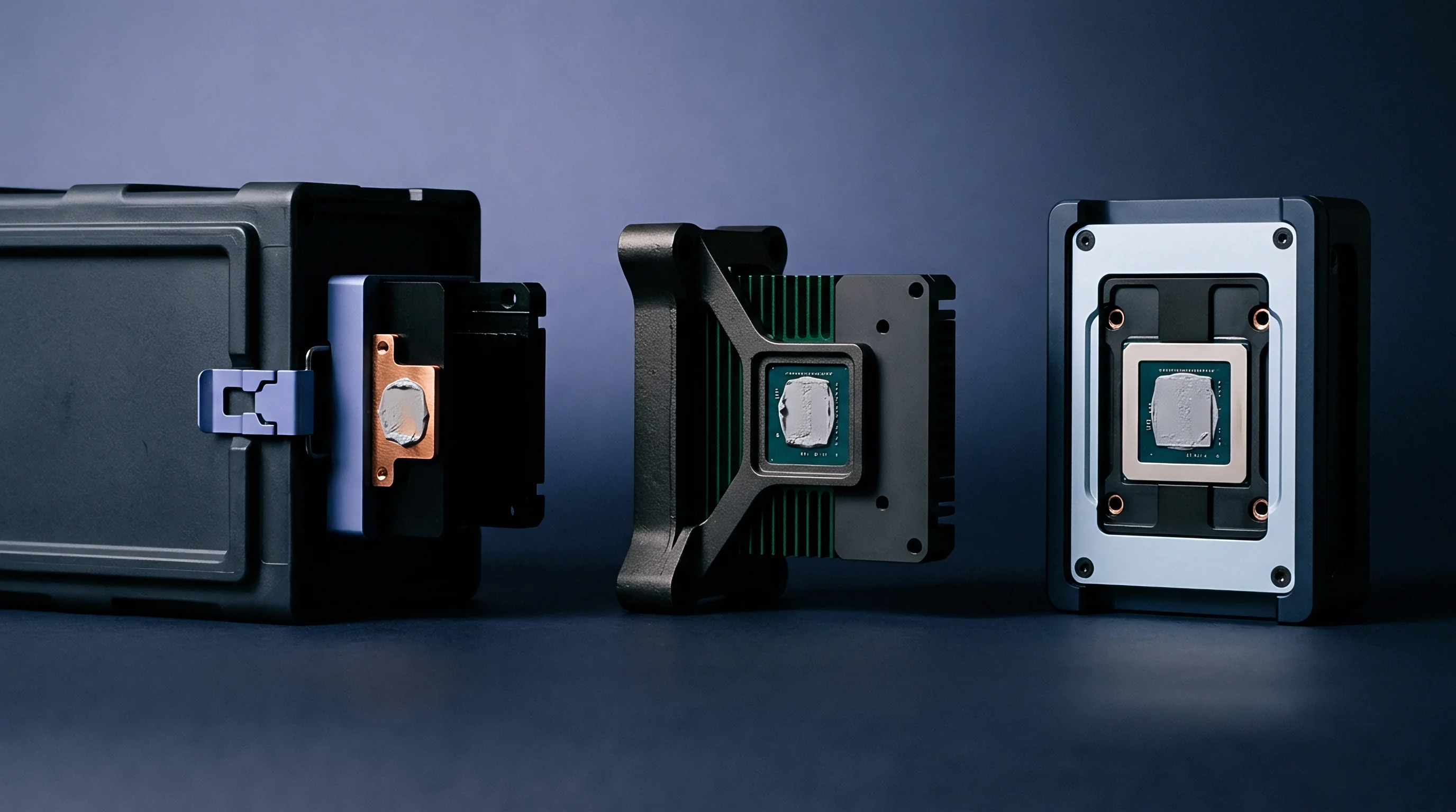
Time-averaged power tracking uses a running energy credit algorithm in modem firmware. Solutions like Qualcomm Smart Transmit, MediaTek Time Averaging SAR, and Apple TAS track a rolling ledger of radiated RF power over standardized integration periods: 100 seconds for frequencies under 3 GHz, 60 seconds between 3 GHz and 6 GHz, and 360 seconds for mmWave thermal metrics. When energy credits run out, transmit power drops by 3 dB.
Energy Credit Accounting and Normalized Exposure Limits
The time-averaging engine balances real-time power output against two configured regulatory benchmarks: absolute maximum hardware transmit power and the continuous power limit needed for compliance during unbroken transmission. When the radio runs at low power, stays idle, or receives downlink data, headroom accumulates in a virtual reserve. The modem then draws on these banked credits to allow full-power bursts when uplink demands spike.
Multi-radio setups rely on normalized exposure summation. When several transmitters operate at once inside the host, each radio translates its real-time output into a normalized SAR fraction, and the algorithm continuously sums these fractions across all active links.
- Threshold evaluation begins when total normalized transmit power reaches ninety percent of the regulatory SAR cap within the sliding 100-second window.
- Power budget reallocation tells secondary radios to step down peak output before the primary cellular modem drains its remaining credits.
- Reserve pool recalculation refreshes available credits every millisecond using real-time feedback from physical layer drivers.
- Emergency power clamp triggers a hardware backoff within ten milliseconds if sideband signaling drops or sensor communication fails.
Energy credits decay continuously. The engine recalculates instantaneous allowances on a tight loop to prevent localized heat buildup in nearby tissue.
| Frequency Band | Regulatory Jurisdiction | Averaging Window Time | Localized SAR Ceiling | Primary Mechanism |
|---|---|---|---|---|
| Sub-3 GHz (Cellular / WLAN) | FCC (US / Canada) | 100 Seconds | 1.6 W/kg (1g Tissue) | Rolling Energy Credit Ledger |
| Sub-3 GHz (Cellular / WLAN) | EU RED / ICNIRP | 100 Seconds | 2.0 W/kg (10g Tissue) | Thermal Time Constant Tracking |
| 3 GHz to 6 GHz (Wi-Fi 6E/7, Sub-6) | FCC / ISED | 60 Seconds | 1.6 W/kg (1g Tissue) | Dynamic Spatial Power Scaling |
| 3 GHz to 6 GHz (Wi-Fi 6E/7, Sub-6) | EU RED / CE | 60 Seconds | 2.0 W/kg (10g Tissue) | Normalized Dual-Radio Summation |
| mmWave FR2 (> 24 GHz) | FCC / Global | 360 Seconds | 10 W/m² (PD Limit) | Pencil Beam Power Density Tracking |
Radiated transmit power balances against human tissue exposure when high burst rates yield to low average duty cycles.

Burst Transmission Management under Deep Fading
Severe multipath fading tests the limits of time-averaging algorithms. When a host enters a deep shadow zone, the base station requests maximum target RF power. The engine permits the transmitter to ramp up to its maximum continuous capability for a short burst, but these high-power bursts burn through banked credits quickly.
Once the reserve hits zero, the algorithm caps output at the continuous baseline rating. Demanding power beyond this floor causes packet drops and triggers physical layer retransmissions, which drain battery in the field. To avoid abrupt hardware throttling that degrades voice or video streams, host software needs to catch impending backoff early and signal upper layers to compress payloads or drop background traffic.
While static limits unnecessarily sacrifice coverage, dynamic time averaging preserves link budget integrity by trading temporal headroom against short burst demands.


Grid
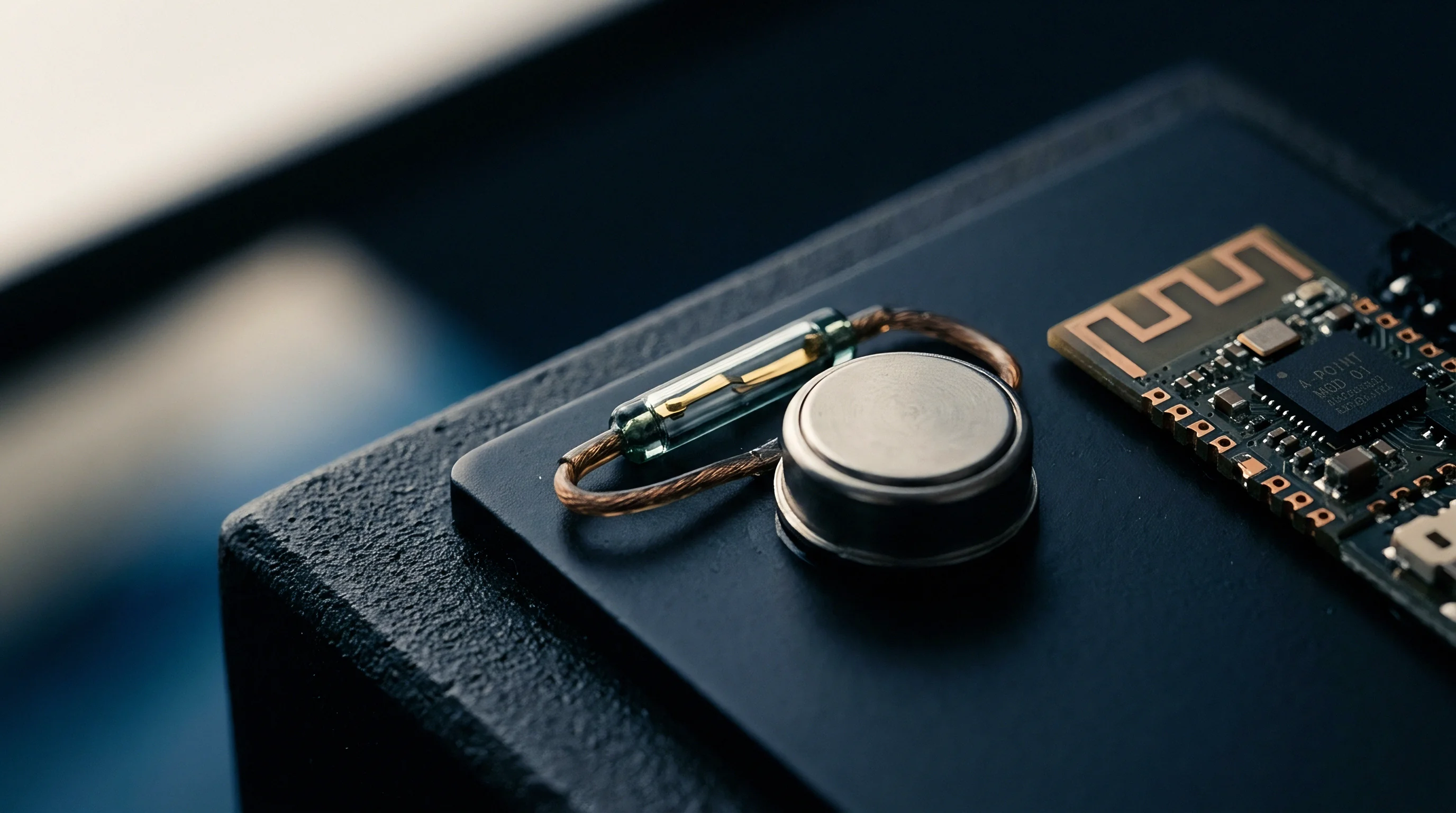
Capacitive sensor arrays around antenna bezels detect human body proximity within three to fifteen millimeters. Modern hosts combine these discrete sensors with hinge-angle sensors, accelerometers, and dedicated SAR controllers. By aggregating raw telemetry from these sources, the host sensor hub determines device posture ~ whether the unit is sitting on a lap, folded into tablet mode, or resting on a wooden desk.

Sensor Telemetry and Detection Thresholds
Capacitive sensors track minute shifts in baseline capacitance as conductive human tissue enters the near-field zone. However, thermal swings, chassis flex, and moisture alter native baselines. This dielectric drift introduces measurement errors, forcing firmware developers to raise detection thresholds and risk triggering false proximity events.
When false triggers occur, the system forces unnecessary radio power backoffs even while resting on an inanimate surface. Sensor controller ICs use ground-shielding traces and self-calibration routines to maintain sensitivity down to 0.1 picofarads of delta capacitance, while micro-controller units filter raw capacitance data with running medians to suppress transient EMI spikes.
- Capacitive Proximity Sensors detect the dielectric signature of human skin within a 15 mm zone around active antennas.
- Hinge Angle Sensors monitor chassis orientation in 2-in-1 convertibles to selectively disable specific antenna arrays.
- SAR Sensor Controllers handle localized threshold math and send interrupt signals directly to module GPIO pins.
- Host Motion Accelerometers differentiate static lap placement from stationary tabletop use.
False proximity triggers degrade network performance by dropping transmit power when human tissue sits outside the reactive near field.

Failure Modes in Proximity Sensing Subsystems
Failures in proximity sensing compromise either multi-radio performance or regulatory compliance. In long-term deployment, hardware and firmware integrations tend to break down at several predictable points.
- Dielectric Baseline Drift occurs when humidity shifts the neutral capacitance baseline, causing power backoff to latch permanently.
- I2C Bus Contention delays interrupt delivery to the host daemon, causing short RF exposure overruns.
- Display Panel EMI Coupling feeds switching noise into unshielded sensor traces, completely masking proximity signatures.
- Postural Misclassification in sensor fusion algorithms misidentifies lap placement as a tabletop surface, missing mandatory regulatory backoffs.
Integrated sensor fusion drivers are intended to eliminate false power reductions, but mechanical chassis tolerances, flex-cable routing parasites, and thermal expansion continuously shift capacitive baselines in practical hardware deployments.

Signal
Communication between discrete radio modules relies on host driver mediation and hardware sideband lines. In modular hosts, the cellular modem typically sits in an M.2 Key B slot on PCIe or USB 3.2, while Wi-Fi 7 and Bluetooth occupy an M.2 Key E slot or soldered logic board placement. Managing shared SAR limits across these radios without latency bottlenecks requires standardized signaling paths.

What Triggers Cross Radio Backoff Coordination Failure?
Coordinated backoff failures happen when host driver software delays cross-module updates during heavy OS loads. Standard driver stacks introduce variable latency when passing power commands: if a cellular modem ramps up power to compensate for a weak signal while Wi-Fi streams at maximum throughput on 6 GHz, combined exposure can breach unity before the driver issues a backoff command.
To bypass OS scheduling bottlenecks, hardware designs route dedicated GPIO sideband lines directly between M.2 slots. These real-time traces carry hardware interrupts straight between radio chipsets without software intervention.
| Active Radio State | Operating Frequency | Allocated Normalized SAR Fraction | Max Transmit Power Allowed | Coexistence Signaling Path |
|---|---|---|---|---|
| 5G NR Sub-6 (Anchor) | Band n78 (3.5 GHz) | 0.60 (60% SAR Budget) | +20.0 dBm | Direct M.2 Sideband Interrupt |
| Wi-Fi 7 (2×2 MIMO) | UNII-5 (5.9 to 6.4 GHz) | 0.30 (30% SAR Budget) | +14.5 dBm | Shared Host OS Daemon (PCIe) |
| Bluetooth 5.4 (eSCO) | 2.4 GHz ISM | 0.05 (5% SAR Budget) | +8.0 dBm | UART / Coexistence Bus |
| System Headroom Reserve | N/A | 0.05 (5% SAR Margin) | N/A | Internal Algorithm Safety Margin |
System architectures implement a structured protocol sequence to enforce cross-radio power allocation without compromising link responsiveness.
- The host communication daemon initializes shared memory structures to track real-time SAR allocations across all installed M.2 radios.
- Cellular modems send high-priority allocation request interrupts over sideband lines before ramping up uplink power.
- The host daemon evaluates the combined exposure ledger against postural and sensor inputs within two milliseconds.
- Wi-Fi chipsets receive hardware-asserted backoff signals, capping maximum MCS rates and lowering transmit power.
- The cellular modem adjusts uplink power with confirmation that total system SAR exposure remains within legal limits.
If sideband signals drop because of trace layout flaws or driver corruption, the default safety policy engages, forcing active radios into conservative static backoffs to maintain legal compliance at the expense of throughput.
Maintaining sub-millisecond synchronization through real-time sideband handshakes across varied host operating systems remains a key challenge for modular hardware developers.

Bench
Laboratory qualification of dynamic power backoff requires synchronized measurements of RF conducted power and spatial E-field intensity. Static SAR testing methods fall short because they assume unvarying transmit power. Validating dynamic time-averaged SAR instead demands automated test platforms ~ such as SPEAG cDASY8 or vector array probes ~ connected directly to base station simulators and RF power meters.

Automated Measurement and Dynamic Test Arrays
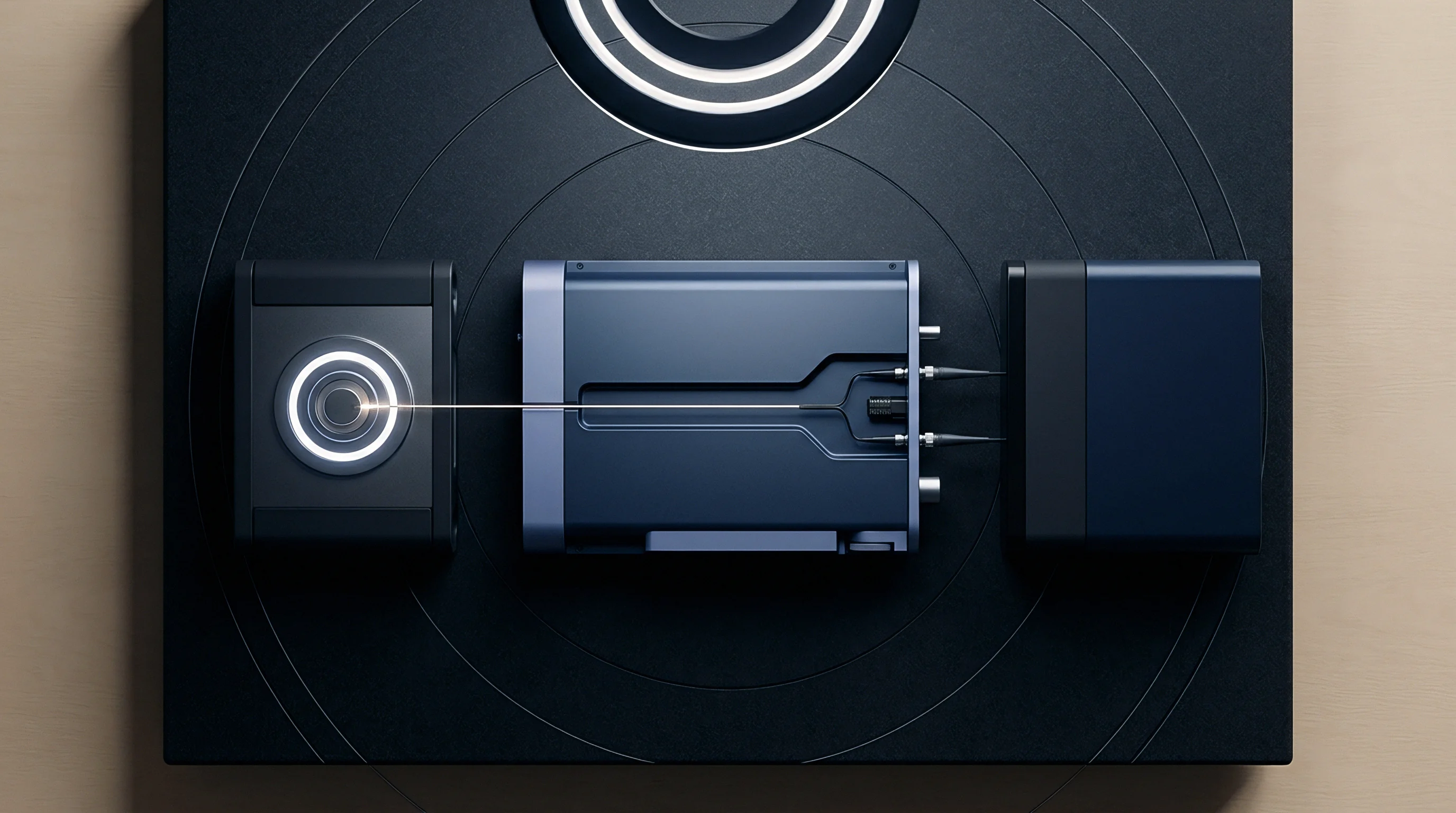
Test setups place high-speed vector probe arrays inside liquid-filled phantom models designed to mimic the dielectric properties of a human torso or lap. The cellular module maintains an active 5G NR link with a call box while programmable attenuators simulate shifting path loss, forcing the modem to scale output power over time.
The test platform logs conducted RF power at the antenna port alongside spatial E-field measurements inside the phantom liquid, comparing continuous spatial peak SAR values against the power ledger reported by modem firmware.
- Signal Generator Synchronization aligns base station fading profiles with probe array timing within 50 microseconds.
- Conductive Port Logging captures directional coupler forward power readings at 100 samples per second on each active path.
- Spatial E-field Scanning measures the 3D SAR distribution field continuously throughout the test sequence.
- Reconstruction Software calculates time-integrated 1g and 10g spatial peak exposure maps over the 100-second regulatory window.
| Test Vector Parameter | Simulated Environment | Power State Transition | Target Compliance Margin | Measurement Uncertainty |
|---|---|---|---|---|
| P-Max to P-Limit Transition | Free Space / Lap Phantom | +23 dBm Burst to +17 dBm Continuous | SAR Ratio ≤ 0.95 | ± 0.8 dB (Vector Probe) |
| Proximity Sensor Trigger Test | 10 mm Phased Phantom Move | Unbacked State to Proximity State | SAR Ratio ≤ 0.98 | ± 1.1 dB (Spatial Reconstruction) |
| Multi-Radio Inter-Tech Swap | Dual-Band Active Stream | 5G NR Handover + Wi-Fi Burst | Normalized Sum ≤ 1.00 | ± 1.2 dB (Combined Probe Array) |
| Sensors Loss Failure Mode | Open Circuit Sensor Bus | Full Power Request to Default Backoff | Immediate Static Backoff | ± 0.5 dB (Conducted Port) |
Compliance verification demands continuous real-time mapping of localized SAR distributions alongside high-speed conducted power telemetry.
Qualification procedures mandate strict adherence to standardized test clauses covering multi-frequency dynamic assessment.
Under IEEE 1528 and FCC KDB 447498 D04 guidelines, dynamic time-averaging validation requires proving that integrated exposure never exceeds static limits under any operational power transition sequence. This forces test labs to log continuous temporal power sequences lasting up to 300 seconds per channel combination, significantly increasing lab testing time and certification costs for complex hosts.
Dispatch
Regulatory filings submitted to certification bodies require verifiable software locks. When modular radios are integrated into a host chassis, the dossier must show that end users cannot bypass sensor thresholds or time-averaging limits using driver modifications, registry edits, or custom OS builds.
Software Integrity and Modular Approval Compliance
The FCC Telecommunication Certification Body (TCB) approval process requires detailed software security documentation under KDB 594280. Integrators must prove that modem firmware signing keys sit locked inside secure hardware boot vaults on the M.2 modules. Any firmware tampering invalidates the grant immediately, exposing the importer of record to enforcement actions and customs impoundment.
Sourcing strategies also have to handle regional software configurations. Radio chipsets store regional lookup tables defining Plimit values for target regulatory zones. A single global host part number must dynamically switch its internal SAR algorithm targets based on active mobile country codes or GPS location fixes.

Commercial Mechanics and Supply Chain Liabilities
Split procurement models create commercial risks when radios and sensor suites come from separate vendors. If an OEM buys a cellular module from one supplier and capacitive sensor ICs from another, compliance failure liability during TCB audits rests entirely on the integrator. Physical antenna detuning inside the host chassis shifts field exposure, rendering standalone module SAR reports invalid.
Procurement teams address this by writing explicit compliance indemnities into component contracts. Agreements require module vendors to deliver qualified driver integration packages ~ including pre-validated sideband signaling daemons and regional table update guarantees ~ before final invoice settlement.
Dossiers submitted for European CE marking under RED Article 3.1a must be archived for ten years post-production. These records hold raw dynamic test logs, capacitive sensor drift calibration profiles, and signed software lock declarations ready for inspection by market surveillance authorities.