FCC Part 15 Modular Certification Rules Baseline Guidelines
FCC Part 15 modular rules allow pre-certified radios in host devices provided shielding, power regulation, labeling, and antenna limits match grant guidelines.


Mandate
Subpart C of Title 47 in the Code of Federal Regulations governs intentional radiators operating without individual license grants. Section 15.212 outlines the precise path by which an intentional radio frequency transmitter obtains approval as an independent assembly, allowing integration into multiple end-use host systems without forcing the host manufacturer to re-certify the underlying radio circuit.
Achieving a full modular grant requires meeting eight strict criteria established by federal regulations. The radio frequency circuitry retains full responsibility for compliance, regardless of the housing, board layout, or power conditioning provided by the host system into which it installs.

The Eight Technical Requirements
First, the module must have its own physical radio frequency shielding. This shield prevents external parasitic capacitance and ambient electromagnetic fields from altering transmitter performance. RF shielding ensures that coupling between the transmitter and host circuitry remains below critical threshold levels.
Second, data and control inputs must be buffered. The module incorporates internal buffer circuitry on all data line interfaces to ensure that the assembly complies with Part 15 limits regardless of the type, timing, or amplitude of signals supplied by the host mainboard. Excessive data rates or invalid logic states fed into the connector cannot drive the transmitter out of authorized bandwidth allocations.
Third, power supply regulation must be integrated directly onto the module printed circuit board, supplying stable direct current to the synthesizer, power amplifier, and baseband silicon. Standard supply rails from host platforms often fluctuate under heavy processing loads; an internal regulator isolates RF frequency stability and harmonic generation from these host power drops.
Fourth, antenna coupling must comply with Section 15.203, requiring either a permanently attached radiator or a unique, non-standard antenna coupler. Standard SMA or sub-miniature connectors fail this standard unless installed behind locked enclosures restricted to qualified service personnel. Trace antennas etched directly onto the module substrate automatically meet this requirement.
Fifth, testing must be performed stand-alone. Qualification testing occurs with the module isolated from any host enclosure, mounted on an open evaluation board connected via a standardized interface ribbon. DC power wires and control lines floating in open air during bench sweeps cannot re-radiate energy above specified limits.
Sixth, the module requires permanent labeling with its assigned certification identifier etched, printed, or affixed onto its structure. When integrated inside a sealed product, the host exterior must display an external label declaring that the device contains the certified module identifier.
Seventh, the transmitter manufacturer must supply comprehensive documentation specifying operating parameters, tuning ranges, duty cycles, and trace routing rules. System integrators follow these instructions to maintain valid certification status.
Eighth, the modular transmitter must meet all radio frequency exposure thresholds defined in mobile or portable usage categories. Higher power modules require explicit minimum separation distances printed directly inside the integration manual.

Full Versatile Approval versus Host Dependent Authorization
A module meeting all eight conditions receives a full modular grant. This grant permits installation into diverse host enclosures without additional intentional radiator filings, provided the integration manual conditions are followed without deviation.
When a radio design fails to satisfy one or more of the eight requirements, standard authorization pathways close. The manufacturer applies for a limited modular approval. Limited modular approval restricts installation to specific host configurations, dedicated enclosures, or host designs produced by the module manufacturer who maintains direct operational control over manufacturing.
Host-dependent testing verifies that the specific power regulation, structural shielding, or custom connector arrangement on the target platform restrains spurious emissions below statutory ceilings. Transferring a limited modular grant to a third-party host integrator requires a Class II permissive change filing or an entirely new equipment authorization file.
Which operational edge cases allow a host integrator to substitute an external antenna on a limited modular grant without invalidating the original test dossier?


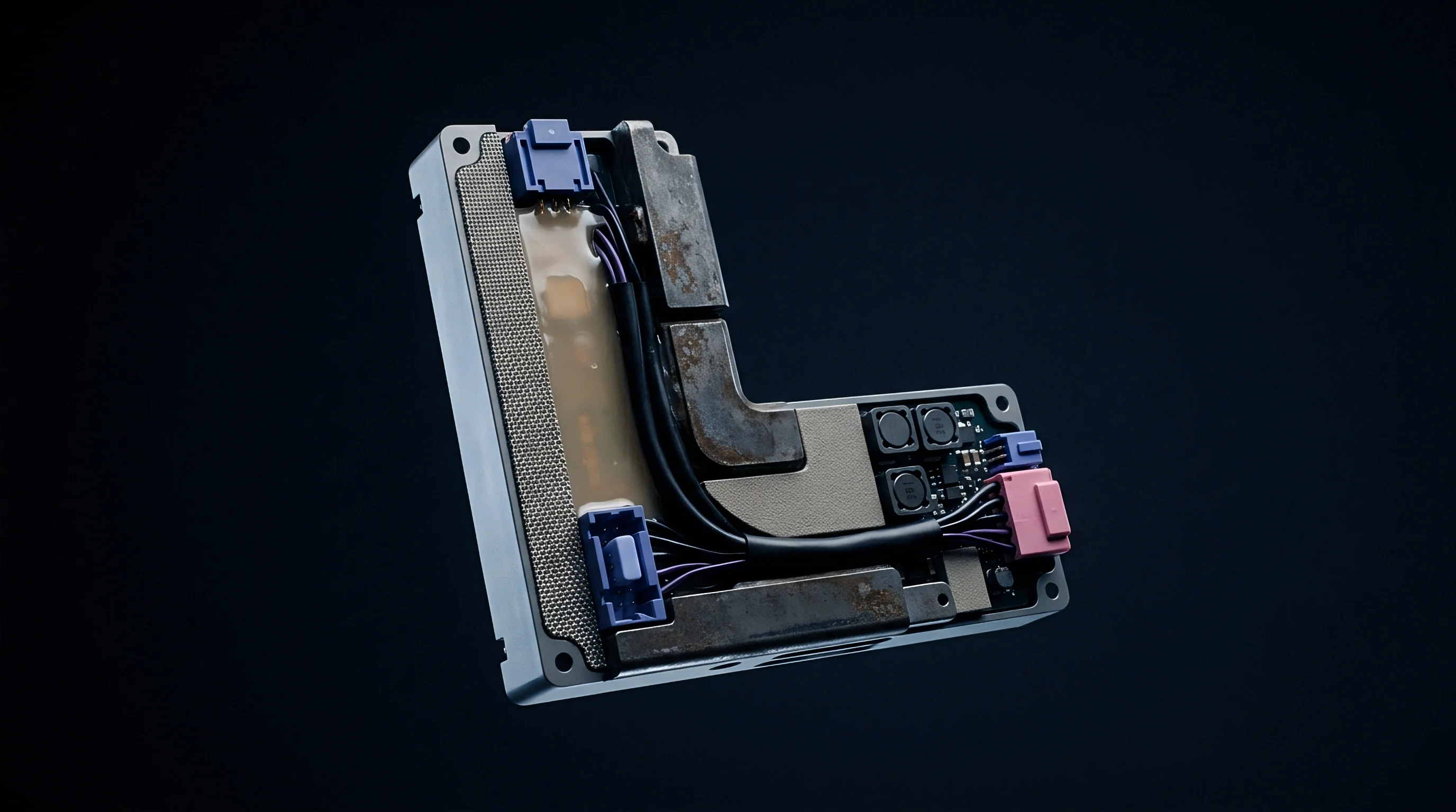
Shield
Enclosing the RF front-end under a grounded metal shield cap prevents host board traces from distorting oscillator stability or inducing unwanted harmonic content. Electromagnetic attenuation provided by the shield maintains baseline radiated emission margins across varying internal host layouts.
Power supply filtering prevents conducted RF currents from flowing backward into host power planes. High-frequency suppression choke beads, alongside decoupling capacitors configured in parallel arrays, shunt spurious switching energy to local ground before conducted noise crosses the module pin boundary.

Radiated Emission Containment Mechanisms
Metal shield cans soldered directly to surrounding ground vias create a Faraday cage around sensitive radio circuits. Direct surface-mount soldering eliminates seam gaps that otherwise function as slot antennas at microwave frequencies. At 2.4 GHz, a seam gap exceeding 6 millimeters radiates energy, converting internal amplifier harmonics into failing radiated field strengths during compliance testing.
Trace routing under the shield edge demands tight spacing parameters. Ground planes on intermediate circuit board layers extend fully beneath the shield perimeter wall. Dropping signal traces through buried vias rather than running top-layer traces under the shield wall prevents RF leakage through the ground plane perimeter.
| Requirement Category | Full Modular Approval (§15.212) | Limited Modular Approval | Compliance Failure Consequence |
|---|---|---|---|
| RF Shielding | Integrated metal shield over front-end components | Shield missing or partial substrate coverage | Host chassis testing mandated for every variant |
| Power Regulation | On-module DC regulation circuit mandatory | Unregulated reliance on host power rail | Voltage sweep testing required across host supplies |
| Antenna Connection | Unique connector or integrated trace antenna | Standard RF connector or raw solder pads | Class II Permissive Change required per host |
| Stand-Alone Test | Complies on open evaluation board without host | Requires host platform during compliance sweeps | Grant restricted exclusively to tested host model |
| Host Labeling | External label states Contains FCC ID string | External label plus specific host warning text | Customs clearance holds or inventory confiscation |
Absence of an internal voltage regulator shifts full supply rail fluctuation testing onto every individual host product configuration.

Power Supply Line Filtering Thresholds
Conducted emissions passing into host power nets must fall below 250 microvolts across the 150 kHz to 30 MHz band. Integrated low-dropout regulators combined with ferrite beads suppress high-frequency ripple originating from the switching power amplifiers.
Decoupling network selection requires low equivalent series resistance ceramic capacitors placed in close proximity to the power amplifier supply pins. A 10-picofarad capacitor paired with a 1-nanofarad capacitor suppresses second and third harmonic feedback along the supply trace, keeping conducted noise within Section 15.207 limits.
Shielding effectiveness drops when ground plane via stitching exceeds one-tenth of the operating wavelength.

Integration
Integrating a certified radio module into an end-use product shifts regulatory responsibilities onto the host manufacturer. The original radio grant covers intentional radiator compliance, but the final composite assembly remains subject to Unintentional Radiator testing under Subpart B.
Host products incorporate digital logic, display drivers, microprocessors, and internal power converters. These non-radio circuits generate electromagnetic noise that requires verification once the radio module installs onto the main system board.

Which Antenna Modifications Trigger Permissive Change Filings?
Swapping an antenna declared on the original modular grant alters the radiator field distribution and total radiated power. Substituting an antenna of the same type with equal or lower gain than the certified antenna preserves compliance without a regulatory filing. Antenna gain calculations evaluate directional peak gain rather than average nominal values.
Introducing a completely different antenna family or increasing directional peak gain demands formal authorization. A Class I permissive change accommodates modifications that preserve field strength values without altering Grant records. A Class II permissive change involves submitting formal lab test data demonstrating compliance under the new antenna configuration, updated under the original grantee authorization file.

Host Evaluation Procedures and Verification Testing
System integrators verify that co-located transmitters operate simultaneously without intermodulation distortion creating non-compliant field strengths. Placing multiple certified radio modules within 20 centimeters of each other generates mixing products that fall outside individual modular grants.
Compliance verification for the composite system follows a structured engineering workflow:
- Review original module Grant notes for antenna gain limits, duty cycle restrictions, and minimum separation distances.
- Inspect host circuit board layout to ensure trace routes matching the module manufacturer trace layout specification exactly when using microstrip reference designs.
- Perform preliminary radiated spurious emission sweeps in an anechoic chamber with all internal digital electronics and radio transmitters operating concurrently at maximum output power.
- Measure intermodulation products generated at signal sum and difference frequencies created by co-located wireless transmitters.
- Document host Unintentional Radiator testing under Subpart B within the final product technical file, retaining records for regulatory inspection.
The host manufacturer holds absolute legal responsibility for composite system compliance with all technical standards applicable to unintentional radiators under Subpart B.
Flawed layout execution that deviates from the module manufacturer trace geometry invalidates the modular grant, converting the end product into an uncertified intentional radiator subject to immediate sales injunctions.


Dossier
Regulatory technical files record every engineering claim, schematic diagram, test result, and user documentation requirement supporting a modular grant. Telecommunication Certification Bodies review these filings to confirm complete alignment with federal rules before issuing equipment authorization certificates.
Document retention demands continuous maintenance throughout the production lifecycle of the modular hardware. Modifying a passive component on the RF path forces a technical file review to determine whether regulatory filings remain valid.

KDB Guidance Documents and Testing Checklists
Office of Engineering and Technology Knowledge Database publication KDB 996369 provides essential procedural directives for modular approvals. D01 covers fundamental modular requirements, D02 addresses host integration considerations, D03 clarifies integration manual guidance, and D04 outlines module integration checklists for host product manufacturers.
System integrators examine Grant condition codes carefully. Restricted grants impose clear operating boundaries that dictate exactly how host platforms handle software power controls, antenna connections, and installation conditions.
| Document Type | Primary Originator | Critical File Contents | Regulatory Audit Role |
|---|---|---|---|
| Grant of Authorization | Telecommunication Certification Body | FCC ID identifier, frequency range, power output, grant notes | Proof of primary radio certification status |
| Integration Manual | Module Manufacturer | Trace routing rules, power limits, antenna lists, exposure distances | Legal boundary instructions for host integrators |
| Subpart B Test Report | Host System Integrator | Radiated and conducted emissions data for non-radio digital circuits | Proof of complete composite system compliance |
| Permissive Change File | Original Grantee or Host Agent | Comparative test data for altered antennas or host enclosures | Authorization for hardware configuration changes |
A transmitter module tested at 18 dBm peak output power behind a 3 dBi gain antenna generates a 21 dBm effective isotropic radiated power limit that host trace layouts cannot exceed.

Grant Notes and Conditions Analysis
Grant note conditions dictate specific deployment restrictions. Single modular grants bearing restricted output conditions mandate that host software prevents end users from altering operational firmware settings to boost output power beyond certified levels.
Integration instructions included inside vendor documentation must detail precise technical requirements:
- Antenna trace parameters define the exact printed circuit trace impedance, physical width, layer stacking, and dielectric constant required when connecting to external u.FL or connector pads.
- Power supply limits specify maximum allowable voltage ripple, peak current capability, and transient response bounds required from the host mainboard.
- Co-location constraints establish exact physical separation distances required when integrating alongside secondary cellular, Bluetooth, or Wi-Fi transceivers.
- Labeling instructions present explicit text formats, font size minimums, and placement locations required on the external host chassis.
- User manual statements mandate precise wording detailing exposure compliance, non-modification warnings, and interference mitigation procedures for end users.
While modular certification simplifies radio testing, it does not eliminate downstream compliance costs for the host integrator.

Exposure
Safety guidelines governing human exposure to radio frequency fields classify devices into mobile or portable operational categories. Transmitters operating within 20 centimeters of a user’s body fall under portable rules, requiring specific absorption rate evaluation unless output power levels fall below strict frequency-dependent exclusion thresholds.
Mobile applications maintain separation distances exceeding 20 centimeters from human bodies. Maximum permissible exposure calculations establish compliance based on power density limits expressed in milliwatts per square centimeter.
SAR Exclusion Limits across Operational Frequencies
Evaluating portable device exposure compliance involves comparing transmitter output power against 1-gram Specific Absorption Rate exclusion limits outlined in KDB 447498. The basic exclusion formula scales with frequency and physical separation distance.
For a 2.4 GHz transceiver operating at 2450 MHz, the basic SAR test exclusion threshold calculation follows this equation:
Power Threshold = (Exclusion Numeric Threshold × Separation Distance in mm) / Sqrt(Frequency in GHz)
Applying standard 1-gram SAR exclusion parameters yields calculated power thresholds:
Threshold = (3.0 × 5 mm) / Sqrt(2.45) = 15 / 1.565 = 9.58 milliwatts
Converting 9.58 milliwatts to decibel-milliwatts produces an exclusion limit of +9.8 dBm conducted power at a 5-millimeter separation distance. A 2.4 GHz Bluetooth module operating at +4 dBm conducted output power (+2.5 mW) falls below this 9.58 mW threshold, exempting the unit from formal SAR chamber testing.
A high-power 2.4 GHz Wi-Fi module radiating +20 dBm conducted output power delivers 100 milliwatts to the antenna. Because 100 milliwatts exceeds the 9.58 milliwatt limit by more than 10 dB, the module requires full SAR evaluation before installation inside a portable host platform operating within 5 millimeters of a user.

Calculated Exposure Budgets for Mixed Transmitter Hosts
Combining multiple transceivers within a single portable host forces fractional SAR calculations. The sum of individual transmitter SAR ratios cannot exceed unity. Fractional exposure sums quantify simultaneous transmission loads across co-located radios.
Host devices frequently accumulate avoidable integration failure modes during production preparation:
- Unshielded trace paths running from the module boundary to external RF connectors pick up digital clock noise from host microprocessors, causing radiated harmonic failures during final compliance sweeps.
- Omitted chassis labeling forces customs delays and retail inventory holds when imported host products lack the external Contains FCC ID statement.
- Unauthorized antenna swaps using higher gain external radiators invalidate the modular grant, turning the host into an illegal intentional radiator.
- Firmware output overrides that allow host software to increase power amplifier registers beyond certified grant values breach regulatory conditions immediately.
- Inadequate ground planes underneath microstrip antenna feed lines detune trace impedance, destroying module match efficiency and causing excessive spurious emissions.
Physical separation distance remains the primary factor in determining portable exposure thresholds.
Evaluating exposure compliance across simultaneous transmitters requires adding the individual SAR exclusion ratios. For a dual-radio host containing a Bluetooth radio operating at 25 percent of its standalone SAR limit alongside a Wi-Fi radio operating at 60 percent of its standalone limit, the total combined ratio equals 0.85. Because 0.85 remains below 1.0, the composite system maintains compliance without triggering additional multi-transmitter SAR testing.
Section 2.909 places explicit legal responsibility for equipment conformity upon the grantee named on the modular authorization certificate.