Conducted Spurious Measurement Protocols for Multi Radio Access Point Architectures
Conducted spurious measurements on multi-radio access points require active port termination, harmonic notch filtering, and concurrent carrier sweep verification.


Tap
Direct RF sampling on concurrent multi-radio hardware demands discrete galvanic paths for each transmitter branch. Enterprise access points integrating Wi-Fi 6E, Wi-Fi 7, Bluetooth Low Energy, and sub-gigahertz 802.15.4 telemetry radios combine high output power with high spatial transmitter density. Physical test points on the printed circuit board must present a strict 50-ohm matched impedance across all active operational bands.
Connecting test equipment directly to micro-coaxial connectors or custom micro-strip launch pads isolates the conducted signal path from radiated chamber reflections. Signal lines cross channels.

RF Multiplexing and Port Extraction
Architectures integrating Wi-Fi 7 enterprise radios alongside Bluetooth Low Energy and sub-gigahertz telemetry radios route signals through internal diplexers. Isolating individual radio signals requires precise temporary modification of RF front-end circuitry. Test engineers insert high-isolation directional couplers or high-frequency micro-coaxial switches immediately following the final power amplifier output stage.
This setup prevents inter-stage loading while extracting high-fidelity spurious spectra under full multi-carrier drive conditions. Combined ports bleed energy.
Isolation between 5 GHz and 6 GHz antenna ports stays above 30 dB during concurrent active transmission to avoid power amplifier compression.
Active port summing nodes present severe measurement risks when concurrent multi-transmitters drive a single wideband antenna structure. High power levels from a 5 GHz transmitter inject backward through triplexer branches into an active 2.4 GHz power amplifier output stage. Non-linear mixing occurring within the un-driven or driven final transistor stage generates false intermodulation products that do not exist during radiated operation.
Laboratory operators resolve this by inserting high-rejection ceramic cavity bandpass filters on each individual branch prior to summing, or by utilizing multi-port automated RF switch matrices capable of terminating inactive paths into precision 50-ohm dummy loads.
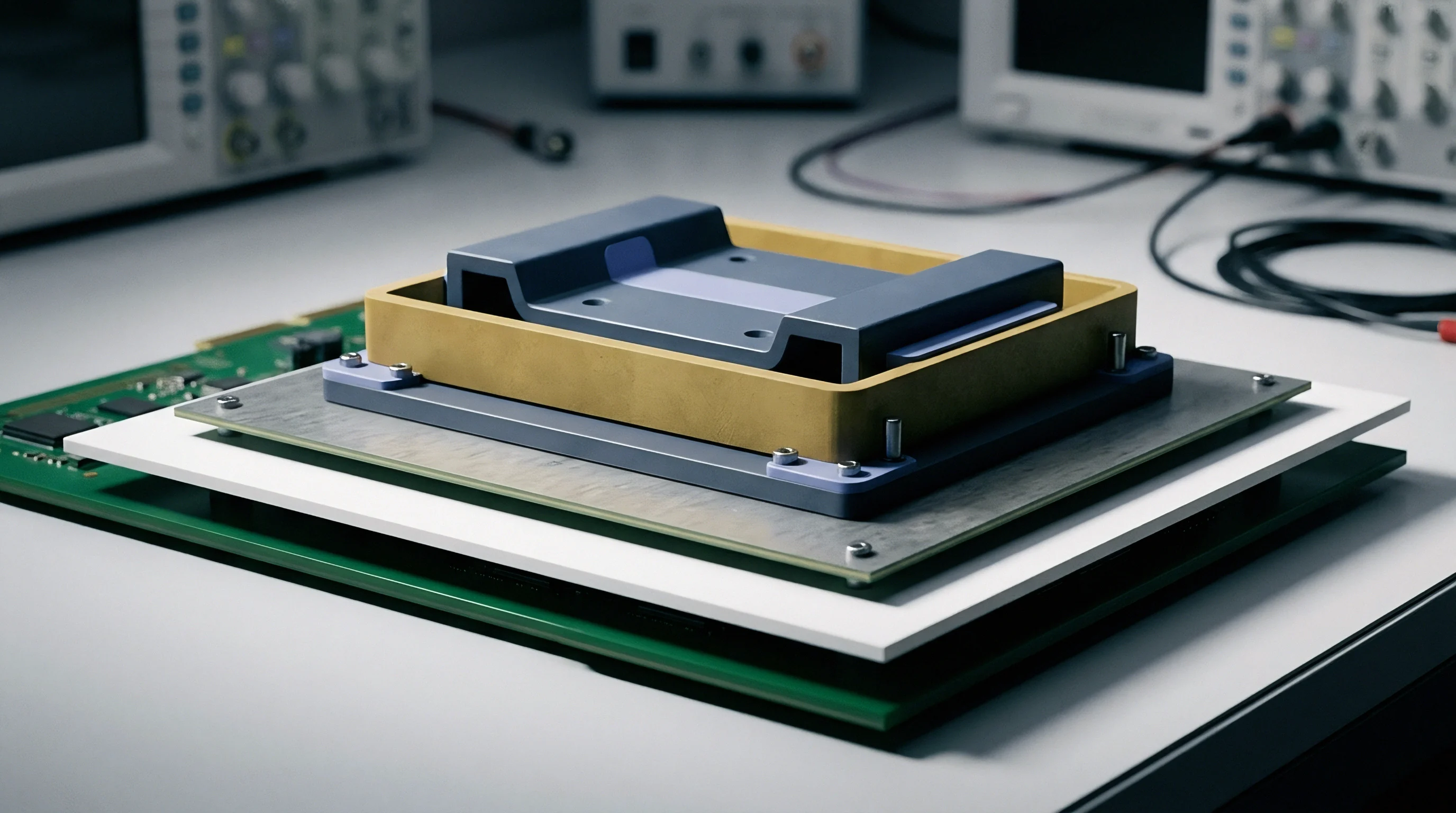
Direct Coupling versus Switch Matrices
Automated test benches employ wideband co-axial passive splitters to sum energy from discrete front-end modules. High power levels hitting the front end of a spectrum analyzer create internal intermodulation distortion within the analyzer mixer stage itself. Insertion of calibrated power attenuators between the RF tap and the measurement receiver protects the front end.
Peak power shifts thermal drift.
Manual cablings introduce variable cable losses, phase shifts, and connector wear that alter high-frequency harmonic readings. Precision RF switch matrices automate path switching between fundamental carrier filters and spectrum analyzer inputs. Calibration files must store frequency-dependent attenuation tables covering every signal path from 9 kHz up to 40 GHz.
Attenuation protects spectrum analyzers.
- Galvanic Micro-Coaxial Taps provide direct insertion points immediately after matching networks, eliminating internal antenna trace coupling while preserving true transmitter output impedance.
- High-Rejection Cavity Filters suppress fundamental carrier frequencies by more than 40 dB, preventing front-end mixer overload inside connected spectrum analyzers.
- Terminated Matrix Switches route active RF streams through automated multi-channel paths while keeping unused ports loaded into precision fifty-ohm terminations.
- Calibrated Directional Couplers sample high-power forward transmission streams with minimal insertion loss, protecting test instruments during multi-carrier stress sweeps.
Failing to isolate combined RF paths before driver stage saturation destroys the front-end switches and renders the sample unusable.


Spur
Intermodulation energy rises when two or more power amplifiers operate simultaneously within a single physical enclosure. Spatial proximity of internal RF traces allows cross-coupling between distinct frequency chains. Non-linear mixing converts fundamental frequencies into unexpected phantom emissions across adjacent operational bands.
Mixers fold frequencies downward.

Intermodulation Dynamics in Multi Transmitter Nodes
Non-linear output stages fold adjacent channel carriers into third-order band products that leak through shared ground planes. Dual-band concurrent operation on 2.4 GHz and 5 GHz generates third-order intermodulation products falling directly into the 7.4 GHz to 7.8 GHz region. Spurious emissions breach thresholds.
When Wi-Fi 6E radios transmit at +26 dBm co-located with a +20 dBm Bluetooth transmitter, mixing products appear at frequency intervals matching the mathematical difference between carrier centers. The amplitude of third-order intermodulation products increases by 3 dB for every 1 dB increase in primary fundamental power. High power saturates front ends.
ETSI EN 300 328 clause 4.3.2.9 enforces an absolute limit of -30 dBm for spurious emissions in the 470 MHz to 694 MHz broadcast band.
Regulatory Out-of-Band Boundaries
Harmonic limits set by international enforcement agencies dictate absolute spectral cleanliness under worst-case duty cycles. Regional authorities maintain distinct limits regarding spurious threshold levels, measurement detector types, and sweep bandwidth definitions.
| Regulatory Standard | Frequency Band | Absolute Limit (dBm) | Detector Type | Resolution Bandwidth |
|---|---|---|---|---|
| ETSI EN 300 328 / EN 301 893 | 30 MHz to 1 GHz | -36 dBm | RMS / Quasi-Peak | 100 kHz |
| ETSI EN 300 328 / EN 301 893 | 1 GHz to 26 GHz | -30 dBm | RMS Average | 1 MHz |
| FCC Part 15.247 / 15.407 | 30 MHz to 40 GHz | -27 dBm / MHz (EIRP equivalent) | Peak / Average | 1 MHz |
| SRRC (China Type Approval) | 30 MHz to 1 GHz | -36 dBm | Quasi-Peak | 100 kHz |
| SRRC (China Type Approval) | 1 GHz to 40 GHz | -30 dBm | Peak | 1 MHz |
Regulatory variance demands that hardware intended for worldwide deployment pass the most stringent overlapping limit line across all target jurisdictions. The European Telecommunications Standards Institute (ETSI) enforces RMS detection modes over high-frequency ranges, whereas the Federal Communications Commission (FCC) emphasizes peak limits alongside average power limits under worst-case duty cycle multipliers.
Transmitter vendors frequently assert that intermodulation spikes originate within the test switch matrix rather than inside their RF module.

Comb
Spectrum analyzer configurations demand exact setting of resolution bandwidth to capture narrow peak responses without rising thermal background levels. Sweep speed governs the probability of intercepting transient spurious bursts generated by digital clock lines and packet preambles. Dynamic range governs margins.

Resolution Bandwidths and Sweep Speeds
ETSI standards demand an integer step in resolution bandwidth when transitioning from in-band margins to out-of-band ranges. Sweep speed impacts sweep time. A narrow resolution bandwidth lowers the displayed average noise floor by 10 dB for every decade reduction in filter width.
The trade-off is an increase in total sweep time, expanding test execution durations exponentially.
Measuring broad frequency ranges requires segmented frequency sweeps. Spectrum analyzers stepping from 30 MHz to 26 GHz split the scan into frequency windows tailored to optimize preselection filters and internal local oscillator stepping. Clock lines radiate internally.
- Connect high-rejection carrier notch filters directly between the EUT antenna tap and the spectrum analyzer front end to suppress primary fundamental signals.
- Inject a calibrated signal generator reference tone into the measurement path to quantify path loss across the entire scan range from 30 MHz to 40 GHz.
- Apply local oscillator path offset tables inside the spectrum analyzer control software to correct real-time amplitude displays.
- Configure trace detectors to maximum peak hold mode and execute minimum three complete frequency sweeps per modulation scheme.
- Switch detector mode to RMS average on identified frequency peaks exceeding threshold margins to verify final regulatory compliance limits.

Noise Floor and Attenuator Budgeting
Consider an enterprise access point transmitting simultaneously on 2.4 GHz at +24 dBm and 5.8 GHz at +28 dBm through a co-located multiplexing port. To prevent internal spectrum analyzer distortion, the input mixer must receive a signal level no higher than -10 dBm. This operational ceiling demands 38 dB of physical front-end attenuation.
A spectrum analyzer presenting a inherent thermal noise floor of -174 dBm/Hz yields a noise floor of -114 dBm in a 100 kHz resolution bandwidth. Adding 38 dB of external attenuation pushes the effective measurement noise floor up to -76 dBm. The ETSI spurious limit line in the sub-gigahertz spectrum sits at -36 dBm, leaving a 40 dB dynamic measurement range.
However, above 1 GHz, where 1 MHz resolution bandwidth is required, the baseline noise floor rises by 10 dB to -66 dBm. Combined with a -30 dBm limit line, the available measurement margin contracts to 36 dB.
Internal filter losses shift the observed noise floor closer to the emission limit line.
Notches suppress fundamental carriers. If a notch filter exhibits an insertion loss of 2.5 dB at the fifth harmonic frequency, the uncalibrated measurement reads 2.5 dB lower than actual radiated or conducted levels. Uncompensated filter roll-off allows non-compliant hardware to falsely pass compliance sweeps, creating legal exposure when regulatory bodies audit off-the-shelf commercial stock.
IEC 62368-1 clause 5.4.1 binds host equipment approval to verified thermal stability during peak multi-carrier output.


Clause
Transmitter modular approvals establish strict operational conditions regarding co-location and simultaneous transmission. Modular grants carry limits. Integrating multiple pre-approved wireless modules into a single commercial host chassis invalidates standalone modular grants if simultaneous transmission conditions were not evaluated on the original filing.

Can Co-Located Modular Grants Bypass Retesting?
Integrators frequently assume that certified modules retain full compliance when placed inside a single plastic chassis. Installing a Wi-Fi 7 module alongside a 5G NR cellular modem triggers FCC requirements for co-located transmitter evaluation. Simultaneous transmission generates intermodulation spurious products that never appeared on standalone modular test reports.
Class II Permissive Changes require conducted intermodulation testing when two modular transmitters utilize shared antenna structures or sit within 20 centimeters of each other. Retesting adds laboratory weeks. Testing schedules must account for full multi-carrier concurrent transmission modes.
| Modification Scenario | FCC Classification | EU RED Requirement | Conducted Test Demands |
|---|---|---|---|
| Antenna trace layout change | Class II Permissive Change | Technical Construction File Update | Full conducted harmonics scan |
| Co-location with new radio module | Class II Permissive Change | Updated Risk Assessment and DoC | Intermodulation spur search |
| Power amplifier bias voltage shift | Class I Permissive Change | Internal Audit Verification | Spot-check band edge and spurs |
| Enclosure shielding material swap | Class II Permissive Change | Re-evaluate EMC and Safety | Radiated spur re-scan required |

Permissive Changes across Regulatory Jurisdictions
Class II Permissive Changes under FCC rules govern physical alterations to layout trace routing or power amplifier biasing. European Union rules under the Radio Equipment Directive (RED) 2014/53/EU shift responsibility entirely onto the final host integrator through the Declaration of Conformity process.
Filings demand sample proof. Integrators assembling multi-radio hosts for European markets must assemble a complete Technical Construction File containing multi-transmitter intermodulation evidence. Relying solely on individual component supplier certificates leaves the host manufacturer fully liable for market withdrawals and customs impoundment.
- Unverified Antenna Trace Changes alter RF output matching, generating out-of-band harmonics that exceed modular grant limits.
- Omitted Intermodulation Sweeps on concurrent radio streams result in automatic rejection during Federal Communications Commission grant application reviews.
- Incompatible Firmware Drivers forcing simultaneous transmission on non-certified channel combinations violate grant operational restrictions.
- Missing Attenuation Compensation in automated laboratory software creates erroneous measurement logs that fail post-market compliance audits.
Shared enclosure grants remain valid only as long as spatial separation between internal antennas matches the reference design exactly.
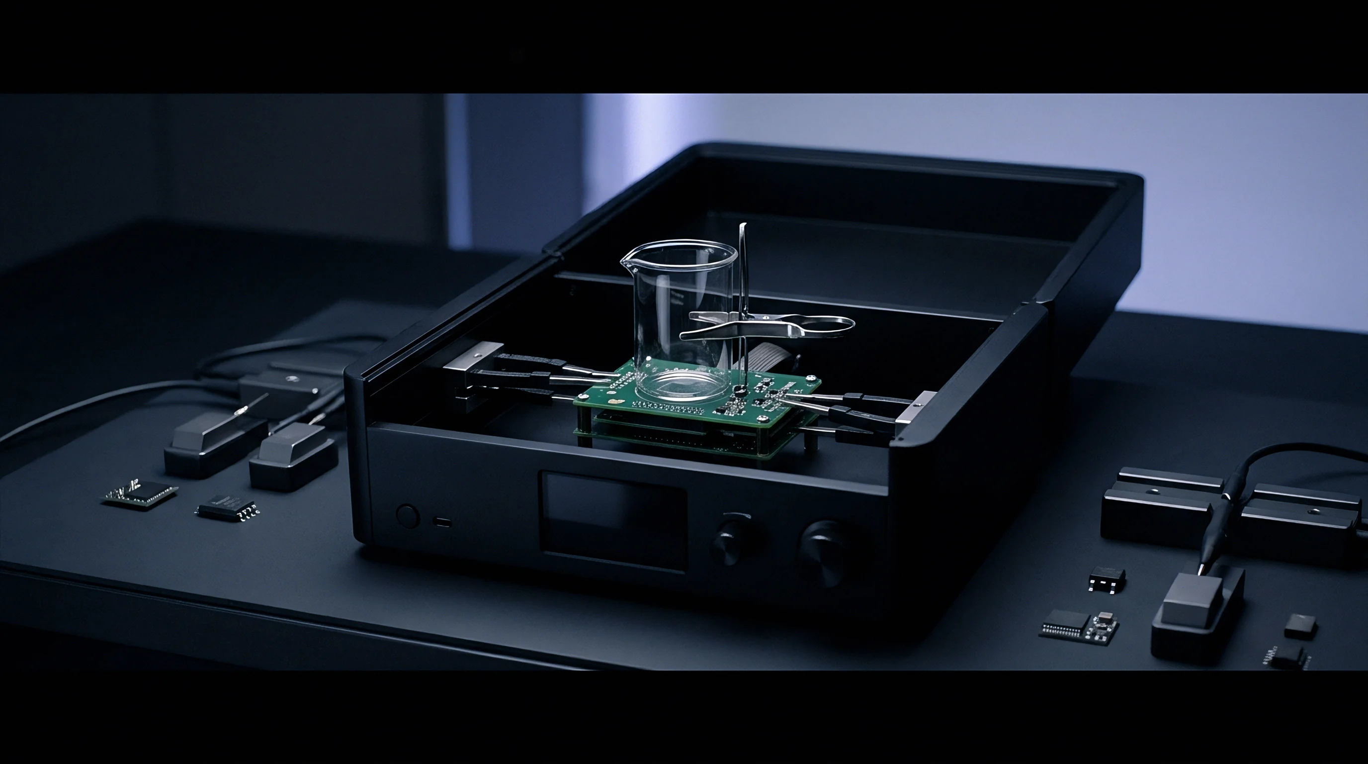

Tariff
Commercial laboratories price multi-radio test campaigns based on occupied chamber hours and setup complexity. Sourcing teams budgeting product development schedules must factor in baseline testing fees, pre-scan debug sessions, and regulatory filing charges. Retest delays push market entry.

Laboratory Hours and Retest Allocations
Prescan runs reveal hidden intermodulation spikes before formal compliance recording begins. Booking accredited test laboratory time costs between 1,500 USD and 2,800 USD per eight-hour shift. Complex multi-radio access points require up to five full shifts solely to cover conducted spurious sweeps across all modulation schemes, spatial stream configurations, and simultaneous transmission modes.
Automated test execution reduces active technician labor but demands initial firmware configuration time. Sourcing practices must require radio module suppliers to provide dedicated, rock-solid engineering test scripts capable of forcing specific channel, data rate, and power output combinations via simple serial commands.
Custom test firmware missing automated frequency toggling adds manual operator hours to the final laboratory invoice.
In-Country Filings and Schedule Mechanics
Local regulatory bodies in Latin America and Southeast Asia require physical sample submission alongside international test reports. Agencies such as ANATEL in Brazil or SDPPI in Indonesia enforce strict local testing protocols that mirror or adapt international standards.
- Firmware Lockup Rejections occur when control software crashes during continuous high-duty-cycle transmission sweeps, forcing complete test sequence restarts.
- Improper RF Adapter Calibrations introduce unaccounted path loss variations, causing artificial limit breaches during high-frequency scans.
- Missing Local Agent Declarations halt customs clearance for physical test samples sent to overseas approval agencies.
- Unresolved Harmonic Spikes identified during final compliance runs force immediate PCB component layout revisions and multi-week launch delays.
Engineers continue to debate whether automated chamber scripting offsets the initial development cost when certifying low-volume enterprise access points across multiple international markets.