Quantifying Passive Intermodulation Degradation Limits in Next Generation Dense Array Module Host Enclosures
Dense array enclosure PIM limits require rigid non-ferromagnetic host joints exceeding plastic deformation thresholds to prevent receiver desensitization.


Junction
Metallic contact interfaces create harmonic distortion when exposed to high-density electromagnetic radiation. In next generation dense array module enclosures, where active antenna arrays sit millimeters away from structural aluminum housings, non-linear physical junctions turn radiated fundamental carrier energy into parasitic spurious emissions. Intermodulation desensitizes high-gain receivers.
RF currents traverse microscopic contact asperities. Higher transmit power accelerates oxidation decay. When two continuous wave signals combine across a non-linear metal junction, they generate product frequencies given by mathematical integer combinations of the fundamental inputs.
In dense multi-carrier beamforming architectures, third-order intermodulation products fall directly into co-located uplink receiving channels, crippling receiver sensitivity without triggering primary transmitter fault alarms.

Physical Mechanisms of Passive Intermodulation
Current flow through micro-asperities generates non-linear voltage drops across structural host seams. Surface roughness exceeds the skin depth. At microscopic scales, two bolted aluminum plates touch only at discrete surface peaks.
These micro-asperities conduct the entire RF surface current induced by adjacent antenna array radiators. High current densities produce localized ohmic heating, altering local resistivity and causing current-voltage non-linearities. Microscopic metal-insulator-metal structures form wherever native aluminum oxide or galvanic corrosion resides between contact points, creating microscopic tunneling diodes directly in the path of returning surface currents.
Ferromagnetic materials introduce magnetic hysteresis into the electromagnetic near-field. Nickel underlayers distort weak receive signals. Fasteners, mounting studs, or alignment pins fabricated from stainless steel or plated with electroless nickel exhibit non-linear magnetic permeability.
As the strong magnetic field from dense array radiator elements penetrates these components, the material’s B-H hysteresis curve distorts the surrounding magnetic field lines, generating high-order intermodulation harmonics independent of physical contact pressure.
At 43 dBm carrier power, a 1 dB torque reduction on housing fasteners increases third-order intermodulation products by 14 dB.

Nonlinear Contact Phenomena in Dense Arrays
Surface imperfections create microscopic point contacts where current density increases dramatically. Metallic contact interfaces create harmonic distortion. Fastener torque dictates joint contact linearity.
Dynamic stress disrupts thin oxide boundaries. In dense active antenna units (AAUs) operating in sub-6 GHz and mmWave bands, host enclosures serve simultaneously as structural chassis, thermal heatsink, and RF shielding cavity. The close proximity of array power amplifiers and antenna elements forces strong surface RF currents onto the internal cavity walls.
Micro-arcing occurs across tiny air gaps between conductive panels when induced RF voltage exceeds the dielectric breakdown threshold of localized oxide films. This non-linear discharge generates wideband burst interference. Thermal expansion cycles compound the problem: as active power amplifiers heat the chassis, thermal gradients cause differential expansion across joint seams, shifting contact pressures and altering the non-linear resistance profile of the enclosure during operation.
- Nonlinear Contact Resistance Microscopic surface roughness creates localized high-current points where electron tunneling causes non-linear harmonic voltage drops across housing joints.
- Ferromagnetic Material Coupling Nickel and iron components generate magnetic hysteresis loops when exposed to strong alternating electromagnetic fields near antenna feed networks.
- Particulate Oxide Boundaries Surface oxidation layers function as metal-insulator-metal tunneling diodes across loose structural interfaces and un-passivated mechanical joints.
- Micro-Arcing at Fastener Interfaces Dynamic voltage breakdown across microscopic gaps in anodized aluminum housings produces broadband RF noise spikes under high RF drive levels.
| Source Mechanism | Physical Interface | Typical PIM3 Level (dBc at 2×43 dBm) | Primary Degradation Driver |
|---|---|---|---|
| Contact Tunneling | Unlined housing lap seams | -95 to -110 | Inadequate mechanical clamping pressure |
| Magnetic Hysteresis | Electroless nickel screws | -80 to -95 | Ferromagnetic material in RF near-field |
| Galvanic Oxidation | Bare aluminum against steel bracket | -75 to -90 | Moisture ingress and atmospheric corrosion |
| Micro-Arcing | Anodized thread engagement | -70 to -85 | Insulative anodization breakdown under voltage |
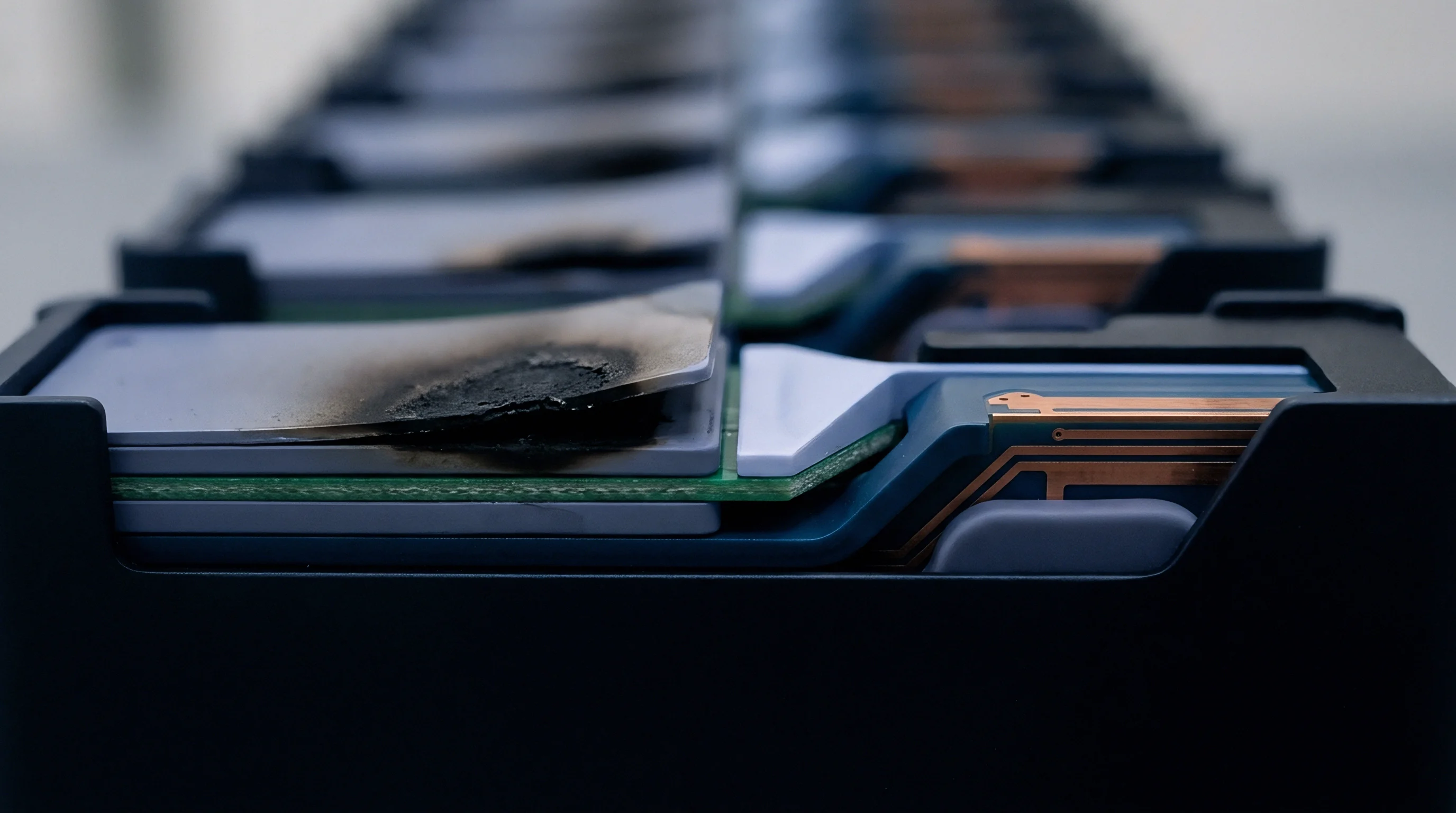
Ignoring joint nonlinearity in structural enclosures forces complete mechanical redesigns after radiated spurious emissions scans fail in certified testing laboratories.

Proximity
Radiated energy in active antenna modules concentrates within millimeter-range boundary layers around radiator elements. Within this reactive near-field region, electromagnetic energy does not propagate as pure plane waves; instead, high reactive field strengths couple directly to structural metal work, radome frames, and housing covers. In dense array configurations with 32, 64, or 128 dual-polarized transceiver channels, the spatial density of transmit power escalates dramatically.
The cumulative electromagnetic field induces intense surface RF currents on every interior metal boundary.

Near-Field Electromagnetic Coupling to Structural Housing
Antenna arrays positioned millimeters from enclosure covers generate intense surface current loops. When two high-power RF signals, such as 3.5 GHz and 3.6 GHz carriers transmitted at +43 dBm (+16 W) per element, strike an enclosure joint, the third-order intermodulation frequency lands at 3.4 GHz (2 x 3.5 GHz – 3.6 GHz). This calculated frequency sits directly inside the 3GPP Band n78 uplink reception window.
Because receive channels operate at sensitivity levels as low as -105 dBm, a third-order intermodulation product generated at -110 dBm inside the host housing degrades the receiver carrier-to-noise ratio, causing dropped connections and reduced data throughput.
Quantifying near-field coupling requires integrating surface current densities over the physical geometry of the host enclosure. The magnitude of induced surface current scales linearly with transmit power and inversely with the distance between radiator patch elements and housing boundaries. Reducing the separation distance between the antenna array backplane and the aluminum rear housing from 15 mm to 5 mm increases surface RF current density by a factor of nine, accelerating non-linear product generation at structural fastener locations.

Multi-Carrier Energy Distribution in Array Elements
Transmitting multiple high-power RF signals simultaneously causes multi-tone spectral overlap. Passive intermodulation desensitizes high-gain receivers. Carrier power shifts third-order amplitude peaks.
When an active array forms multiple simultaneous beams, adjacent radiator elements operate with phase variations that shift the physical location of constructive field intensity across the host frame. High-intensity RF hot spots sweep across structural seams during dynamic beamforming operations, causing temporal fluctuations in passive intermodulation levels.
Whether dynamic phase variation in multi-beam massive MIMO array configurations predictably cancels or constructively sums near-field passive intermodulation distortion remains an open analytical question in high-density enclosure design.


Scan
Bench testing for passive intermodulation demands ultra-clean signal sources and dynamic mechanical stimulation. Standard S-parameter measurements using network analyzers fail to reveal non-linear contact characteristics because measurement signal levels remain in the milliwatt range. Passive intermodulation testing demands continuous high-power stimulus, typically utilizing two +43 dBm continuous wave signals fed through low-PIM duplexers into the device under test while monitoring low-level intermodulation products with high-dynamic-range spectrum analyzers.

Does Chamber Vibration Mask High-Order Intermodulation Products?
Dynamic mechanical shaking reveals transient joint instability during sweeping power cycles. Static passive intermodulation bench tests under-report field failure rates because structural host enclosures experience wind loading, thermal cycling, and physical vibration on telecom towers. Applying controlled physical vibration in according to IEC 62037 guidelines during two-tone testing forces loose metal interfaces to micro-shift, exposing latent contact non-linearities, flaking metal platings, and loose mechanical fasteners that appear compliant during static laboratory sweeps.

Standard Measurement Setups and Residual Instrument Limits
Laboratory test instruments maintain residual signal floors near minus one hundred twenty-five decibels relative to carrier. Dynamic stress disrupts thin oxide boundaries. Test cables introduce residual intermodulation floors.
High-precision testing demands strict low-PIM measurement practices. Standard RF test cables, adapters, and loads generate their own non-linear distortion when driven by high-power tones. Test instrumentation residual intermodulation levels must be qualified below -125 dBm (-168 dBc relative to 2x +43 dBm carriers) prior to evaluating host enclosure performance.
Non-compliance with ETSI EN 301 908-1 receiver desensitization boundaries invalidates modular radio approvals upon host enclosure integration.
Evaluating an active array host enclosure requires a structured sequence of continuous-wave and dynamic physical stress tests:
- Calibrate continuous-wave signal sources through ultra-low-noise power amplifiers to deliver dual +43 dBm tones at the test chamber interface.
- Measure residual test equipment intermodulation floor using a certified low-PIM termination load to verify baseline levels stay below -125 dBm.
- Position the host enclosure on a non-conductive dielectric test fixture inside an anechoic chamber to isolate radiated environment reflections.
- Attach active antenna array modules to the host enclosure using specified production torque settings on all mechanical fasteners.
- Inject fundamental carrier frequencies across operational bandwidth limits while sweeping receiver spectrum analyzer channels to record third-order and fifth-order intermodulation spectrum masks.
- Apply controlled dynamic impact taps using a calibrated non-metallic hammer adjacent to host mechanical seams while monitoring peak intermodulation excursions.
- Subject the complete enclosure assembly to continuous thermal cycling from -40 degrees Celsius to +85 degrees Celsius during live continuous-wave RF excitation.
| Test Parameter | Standard Value (IEC 62037) | Target Instrument Floor | Pass Criteria Limit |
|---|---|---|---|
| Carrier Power (P1, P2) | +43 dBm (20 W) per tone | Not Applicable | Fixed setpoint +/- 0.3 dB |
| Dynamic Vibration Frequency | 10 Hz to 55 Hz sinusoidal | -130 dBm residual | No excursion > 10 dB above floor |
| PIM3 Intermodulation Level | Calculated at 2f1 – f2 | -125 dBm (-168 dBc) | -110 dBm (-153 dBc) maximum |
| PIM5 Intermodulation Level | Calculated at 3f1 – 2f2 | -135 dBm (-178 dBc) | -120 dBm (-163 dBc) maximum |
Enclosure vendors routinely claim that elevated passive intermodulation floor figures originate from test chamber cable assembly wear rather than structural housing plating defects.

Coating
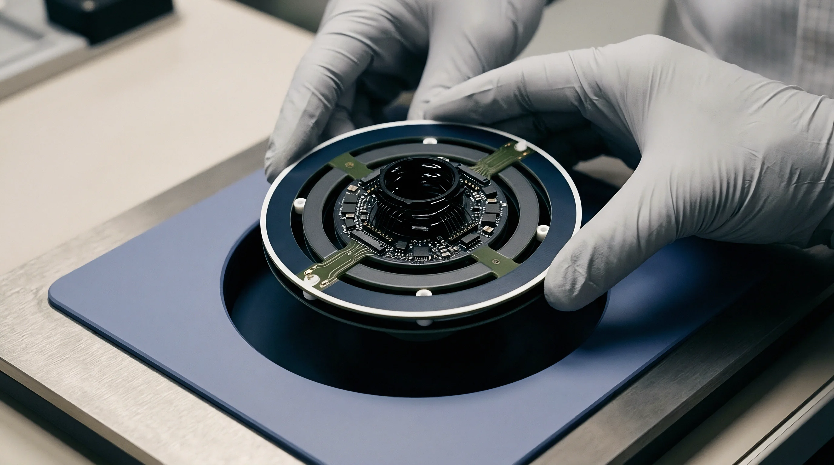
Surface finish selections directly govern mechanical contact stability and oxidation rates. Unfinished aluminum rapidly oxidizes in standard atmospheric conditions, forming a dielectric film that breaks down non-linearly under high RF field strength. Selecting appropriate metallic plating chemistries for internal cavity surfaces and joint interfaces eliminates tunneling junctions and micro-arcing.
Passivation treatments prevent surface oxide buildup. Plating thickness must exceed several RF skin depths at the operating frequency to ensure surface currents flow entirely within the high-conductivity plating layer rather than penetrating into base alloy impurities.
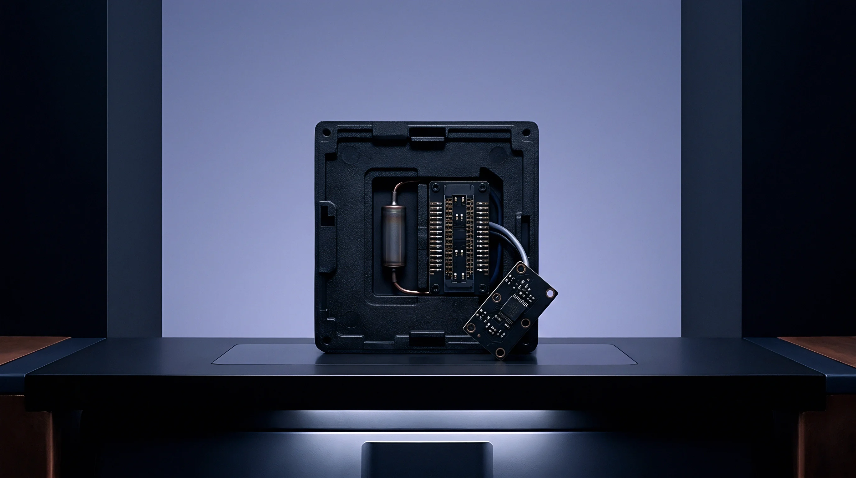
Plating Chemistries and Passivation Options
Silver and tri-metal alloys form low-resistance contact interfaces without magnetic hysteresis. Silver plating provides maximum electrical conductivity and low intermodulation response, but requires anti-tarnish passivation coatings to prevent oxide and sulfide film formation in humid environments. Tri-metal plating (a ternary alloy of copper, tin, and zinc) offers high conductivity, robust wear resistance, and non-magnetic performance at lower cost than silver, making it a common standard for structural RF cavity covers.
Electroless nickel plating contains iron group elements that introduce severe magnetic hysteresis into near-field boundaries. Standard nickel underlayers underneath gold or tin platings act as strong non-linear intermodulation sources. High-phosphorus electroless nickel exhibits lower magnetic permeability than low-phosphorus formulations, but remaining non-ferromagnetic alloys like copper or silver underlayers remain necessary when host enclosures operate near active array radiator lobes.

Galvanic Corrosion and Torque Hysteresis
Humidity and atmospheric salt create conductive electrolytes across adjacent dissimilar metal interfaces. Galvanic mismatch accelerates interface corrosion rates. When aluminum host housings join with stainless steel fasteners or brass connectors, the electrochemical potential differential generates localized galvanic corrosion.
Corrosion products expand unevenly, disrupting mechanical contact pressure and creating non-linear metal-insulator-metal oxide barriers over time.
Structural contact pressure must remain beyond the plastic deformation threshold of the surface finish under cyclic thermal expansion.
- Anodization Creep Insulating anodic oxide coatings bleeding onto structural RF contact surfaces cause high-voltage dielectric breakdown and micro-arcing.
- Silver Sulfide Tarnishing Atmospheric sulfur exposure forms semiconducting silver sulfide surface films that increase non-linear contact resistance across unsealed housing seams.
- Micro-Cracking Under Stress Brittle plating layers applied over soft aluminum substrates fracture under mechanical fastener torque, exposing underlying native oxides to surface RF currents.
- Gallium and Zinc Migration Low-melting-point plating constituents migrate under elevated operating temperatures, creating non-uniform conductivity profiles across structural joint interfaces.
Plating interfaces combining dissimilar metals with high galvanic potential differences inevitably develop non-linear oxidation barriers when subjected to outdoor environmental moisture.


Allowance
Regulatory bodies enforce strict spectral mask boundaries to prevent co-located receiver desensitization. The Federal Communications Commission (FCC) in the United States and the European Telecommunications Standards Institute (ETSI) under the Radio Equipment Directive 2014/53/EU establish absolute limits on out-of-band and spurious emissions. When passive intermodulation products generated within a host enclosure radiate out of the radome, they count against the integrated transmitter’s total spurious emission allowance.

3GPP and Regulatory Spurious Emission Thresholds
Base station specifications establish explicit limits on radiated harmonic signals across commercial spectrum bands. Under 3GPP TS 38.104 for 5G New Radio base stations, mandatory radiated spurious emission limits require out-of-band signals to stay below -13 dBm measured in a 100 kHz bandwidth for frequencies between 30 MHz and 1 GHz, and below -13 dBm in a 1 MHz bandwidth for frequencies above 1 GHz. In critical co-existence frequency bands, regulatory authorities impose stringent protection limits as low as -49 dBm or -59 dBm to protect adjacent public safety or aeronautical radio services.
Passive intermodulation generated in host enclosures poses a severe threat to compliance because third-order products generated by dual +43 dBm carrier signals easily exceed -13 dBm radiated power if structural shielding cavity seams lack adequate RF contact integrity. Spurious products degrade receiver noise floors. A third-order intermodulation product reaching -80 dBm inside the radome cavity exceeds standard transmitter spurious emission limits by over 60 dB, rendering the radio system illegal to deploy.

Modular Approval Limits and Host Hostile Coupling
Integrating a pre-certified transmitter module into a non-linear enclosure alters radiated performance profiles. Grant conditions for modular radio approvals mandate that host integrators assume responsibility for compliance issues introduced by host mechanical structures. If an approved transmitter module causes an host enclosure joint to generate passive intermodulation that breaks out-of-band emission boundaries, the modular grant no longer covers the finished host assembly.
- Regulatory Mask Failures Radiated third-order passive intermodulation products breaching regional out-of-band emission limits halt equipment sales and trigger market clearance revocations.
- Uplink Receiver Desensitization Internal passive intermodulation landing within receiver operating bands elevates the receiver noise floor, forcing cell site coverage area contraction.
- Class II Permissive Change Requirements Non-linear mechanical enclosure modifications that elevate radiated spurious emissions demand expensive regulatory re-filings and lab evaluations.
- Co-Location Compliance Violations Inter-modulation products generated by third-party antennas mounted on shared tower structures breach mutual operator non-interference lease agreements.
Under FCC Part 27 Section 27.53, passive intermodulation falling into adjacent protected bands transforms a class I permissive change into a mandatory class II permissive filing that halts commercial shipping until laboratory evaluation completes.

Audit
Quality management protocols at the manufacturing plant govern enclosure compliance before assembly. Mitigating passive intermodulation degradation limits demands rigorous incoming inspection, controlled fastener assembly parameters, and traceable plating verification protocols. Mechanical drawings must specify exact contact surface flatness tolerances, surface finish roughness parameters (Ra under 0.8 micrometers), and precise fastener torque limits.

Factory Acceptance Criteria and Fastener Torque Control
Assembly lines implement automated torque calibration drivers to ensure uniform contact pressure. Fastener torque dictates joint contact linearity. Thermal cycles alter physical contact pressure.
Inadequate torque leaves micro-gaps that invite micro-arcing and oxide tunneling, while excessive torque strips threads or causes localized plastic deformation of plating layers, creating flaking surface debris that generates dynamic intermodulation spikes. Structural joints require calibrated screw pattern sequences to distribute clamping forces evenly across conductive gasket interfaces.
Quality engineers perform batch sampling of housing die-castings using X-ray fluorescence (XRF) analyzers to verify plating composition and thickness. Incoming inspection acceptance rules reject enclosure shipments exhibiting ferromagnetic contamination, flaking plating layers, or surface oxidation spots exceeding established surface area thresholds.

Procurement Contract Protections and Recourse
Purchase orders require explicit compliance certificates before shipment authorization. Sourcing practices must embed passive intermodulation compliance requirements into structural enclosure procurement contracts. Standard mechanical housing guarantees covering dimensional tolerances fail to protect buyers against non-linear electrical degradation discovered during final radio system qualification.
Consider a practical commercial scenario: a sourcing team purchases 5,000 die-cast aluminum host enclosures for a 5G active antenna deployment at a unit cost of 180 USD per housing. Standard incoming mechanical inspection passes the batch based on dimensional fit and surface cosmetic appearance. During final integration testing with active array electronics, 12 percent of assembled units exhibit elevated third-order passive intermodulation reaching -95 dBm, breaching the -110 dBm system pass specification limit under dynamic vibration.
Scrapping 600 non-compliant enclosures results in a direct material loss of 108,000 USD. Chamber re-testing fees at accredited third-party test laboratories run 2,500 USD per day, adding 25,000 USD in unplanned qualification costs over a two-week re-evaluation campaign. Production line downtime charges incurred while waiting for replacement parts run 15,000 USD per week.
Without explicit passive intermodulation performance guarantees and supplier financial indemnity clauses in procurement purchase orders, the host integrator absorbs the full 148,000 USD expense alongside a six-week market launch delay.
Factoring non-linear joint compliance into initial host enclosure drawings prevents late-stage re-engineering cycles, protecting launch windows and eliminating unplanned lab retests.