Resolving Host Enclosure Resonances and Spurious Discrepancies in Embedded Radios
Resolving host enclosure resonances relies on identifying cavity modes and sealing seam apertures before submitting embedded radios for regulatory scans.

Mesh

Cavity Resonance Fundamentals in Metal Enclosures
Conductive metallic boundaries create closed electromagnetic cavities around integrated transmitter circuit boards. When an embedded radio module operates inside a metal or metal-plated housing, high-frequency energy radiated by traces, clock lines, or power amplifier front-ends reflects continuously off internal chassis walls. These internal reflections set up standing wave patterns at discrete frequencies determined by the enclosure’s physical geometry.
At these resonant frequencies, internal field strengths expand significantly, overwhelming board-level filtering and driving energy surges through housing seams.
Calculating exact cavity mode frequencies relies on determining the rectangular or cylindrical enclosure dimensions. For a rectangular chassis of width a, height b, and depth d, the theoretical resonant frequencies follow the standard waveguide cavity relationship:
f_mnl = (c / (2 pi sqrt(mu_r epsilon_r))) sqrt((m pi / a)^2 + (n pi / b)^2 + (l pi / d)^2)
Here, c represents the speed of light in free space, while m, n, and l represent mode integers corresponding to field variations along each physical axis.
Inside a ten-centimeter aluminum chassis, cavity resonances elevate harmonic emissions by up to eighteen decibels at five gigahertz.
A transmitter operating at 2.4 GHz or 5.8 GHz generates harmonics that naturally align with these chassis cavity modes. When a harmonic frequency matches a chassis mode, the internal chassis acts as a high-Q resonator. Transmitted signal energy builds up inside the housing rather than dissipating cleanly, causing board-level shielding cans to leak reactive energy into adjacent structural spaces.
Aperture Coupling and Slot Radiation Effects
Unshielded seams, display cutouts, and ventilation openings transform smooth conductive boundaries into unintentional slot radiators. Surface currents induced on internal metal walls encounter high electrical impedance when meeting structural splits, forcing high-frequency currents to detour around apertures. This interruption in surface current trajectories generates intense electric fields across mechanical gaps, effectively creating slot antennas that radiate high-frequency energy into the external environment.
When an enclosure opening reaches a length equal to half the wavelength of an internal resonant frequency, the aperture achieves maximum radiation efficiency. Fasteners placed too far apart along conductive seams turn mechanical mating joints into continuous series of resonant slots. Enclosure joints without continuous conductive gaskets degrade shielding effectiveness by twenty to forty decibels, allowing internal standing wave spikes to escape directly into compliance measurement environments.
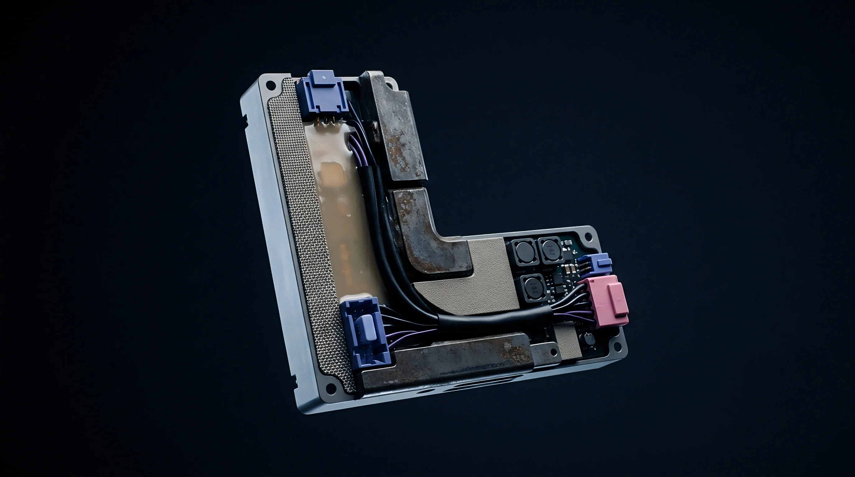
Chassis internal structural supports, battery retention brackets, and board mounting standoffs alter internal cavity volume definitions. These metallic structural elements create complex multi-cavity networks with coupled resonances. Energy transferred between adjacent sub-cavities through internal cutouts creates unexpected spurious peaks at frequencies that do not correspond to primary chassis outer dimensions.
Ignoring internal standing wave formation forces engineers into emergency redesign cycles after preliminary compliance scans reveal severe radiated emission limit breaches.
Scan

Turntable Azimuth and Antenna Polarization Mismatches
Compliance measurement facilities use three-meter or ten-meter semi-anechoic chambers to record field strength profiles. When evaluating embedded radios inside host devices, test engineers position the complete product on a motorized turntable while sweeping a receiving antenna between one and four meters in height across vertical and horizontal polarizations. Radiated emissions originating from host enclosure resonances exhibit extreme directivity compared to isotropic board-level emissions, yielding sharp narrow-beam radiation spikes that appear and disappear over narrow turntable rotation angles.
A product that passes a quick prescan with fixed turntable angles often fails full compliance sweeps when rotated in three-degree increments. Sharp structural radiation lobes align with the receiving antenna at specific rotation azimuths, producing sudden spurious spikes that exceed regulatory thresholds by substantial margins.
| Enclosure Structural Material | Dominant Coupling Mechanism | Observed Peak Discrepancy Range | Turntable Directivity Profile |
|---|---|---|---|
| Die-Cast Aluminum Shell | Seam Surface Current Interruption | 12 dB to 19 dB | Highly Directive Narrow Lobes |
| Conductive-Painted ABS Plastic | Non-Uniform Coating Impedance | 6 dB to 14 dB | Broad Asymmetrical Spikes |
| Molded Carbon Fiber Composite | Anisotropic Material Conductivity | 8 dB to 16 dB | Frequency Dependent Nulls |
| Sheet Metal with Fastener Gaps | Resonant Slot Antenna Coupling | 15 dB to 24 dB | Sharp Multidirectional Peaks |
Differences between conducted emissions measured at antenna ports and radiated emissions recorded in semi-anechoic chambers frequently puzzle engineering teams. An embedded radio module delivering clean conducted harmonic performance under fifty-ohm dummy load tests can display severe radiated harmonic failures once installed inside a metal host housing. The host enclosure converts non-radiating near-field magnetic energy into far-field electromagnetic waves through reactive cavity coupling.

What Triggers Spurious Spikes in Host Radiated Scans?
Internal cabling harnesses and ungrounded chassis heat sinks capture reactive near-field coupling and transfer high-frequency energy outside the chassis. When a flexible printed circuit or wire harness passes near an active cavity resonance node, high-frequency electric fields induce common-mode currents onto cable conductors. The cable then acts as a secondary antenna, carrying RF currents past housing boundaries and radiating energy directly into free space.
The following physical mechanisms commonly produce unexplained spurious emissions during formal compliance scans:
- Seam Impedance Discrepancies High electrical resistance across mating chassis halves breaks surface current continuity, converting mechanical splits into efficient radiators.
- Unterminated Cable Sheaths Internal ribbon cables passing through resonant cavity volumes act as driven monopoles, carrying internal RF energy through housing gaps.
- Floating Heatsink Coupling Large metallic cooling structures positioned near RF front-ends acquire parasitic charges and re-radiate energy at harmonic frequencies.
- Stiffener Rib Waveguiding Internal plastic ribbing lined with decorative conductive paint creates narrow channels that guide surface currents toward open interface ports.
Engineers often confuse board-level harmonic noise with structure-induced electromagnetic cavity amplification.
Discrepancies between pre-compliance near-field probe sweeps and formal far-field automated scans occur when near-field tools fail to capture distant phase alignment across large housing surface areas. Near-field magnetic probes detect local current concentrations but miss phase-coherent radiation from entire chassis seams, leading test teams to misidentify primary spurious sources.
Fully qualified radio hardware is often assumed to guarantee compliance regardless of enclosure geometry, though surrounding metal structures can still induce non-compliant emissions.
Filter
Absorptive Material Placement and Wave Dissipation
Attenuating internal standing waves relies on introduced losses and continuous conductive boundary integrity. Installing thin elastomeric microwave absorbers within host cavities converts high-frequency magnetic fields into heat energy, lowering cavity quality factors and suppressing standing wave peaks. Silicon-based absorber sheets loaded with carbonyl iron powder or ferrite particles attenuate internal reflections when placed precisely at magnetic field maxima inside the chassis.
Placing absorptive materials over electronic components without analyzing cavity field distributions wastes material and increases manufacturing expenses. Magnetic field maxima occur along conductive chassis walls where standing wave surface currents reach maximum intensity, whereas electric field maxima sit near cavity centers. Securing absorber materials directly to internal metal chassis faces yields optimal wave attenuation while minimizing material volume.
| Suppression Technique | Targeted Frequency Band | Typical Attenuation Range | Mechanical Impact |
|---|---|---|---|
| Carbonyl Iron Absorber Sheets | 1 GHz to 18 GHz | 4 dB to 12 dB | Adds 0.5mm to 1.5mm Thickness |
| Beryllium Copper Finger Stock | 100 MHz to 10 GHz | 15 dB to 30 dB | Increases Compression Force |
| Conductive Elastomeric Gaskets | 500 MHz to 12 GHz | 20 dB to 40 dB | Requires Mating Surface Groove |
| PCB Ground Via Perimeter Stitching | 2.4 GHz to 6 GHz | 6 dB to 15 dB | Consumes Board Perimeter Space |
Mechanical engineers must maintain continuous contact pressure along chassis perimeter gaskets to close aperture gaps. Using conductive foam strips, beryllium copper spring fingers, or form-in-place conductive elastomers ensures continuous ground electrical conductivity across mating seams, preventing surface current interruptions.

Board Edge Shielding and Ground Plane Stitching
Continuous ground vias placed at intervals below one-tenth of the guided wavelength suppress surface wave propagation along printed circuit board perimeters. Edge-stitching vias connect top, inner, and bottom ground planes along circuit board boundaries, creating a conductive wall that prevents radio frequency noise from escaping PCB substrate edges into host enclosure cavities.
Step-by-step diagnostic procedures allow engineering teams to systematically identify and eliminate internal host resonances:
- Locate high-intensity near-field hotspots inside the housing using a magnetic field probe connected to a spectrum analyzer.
- Calculate theoretical cavity mode frequencies corresponding to internal physical dimensions to match observed spectral peaks.
- Apply elastomeric absorptive sheets directly over metallic regions exhibiting maximum magnetic field density.
- Install conductive gasket strips along housing mating seams to reduce aperture length below one-tenth of the targeted harmonic wavelength.
- Re-run preliminary radiated emissions sweeps across all turntable azimuths to confirm suppression effectiveness.
Physical shielding performs only as well as the electrical continuity across its mechanical seams.
Integrating board-level shielding cans directly over active transceivers and power management units prevents raw RF energy from exciting host chassis cavities. Shielding cans must bond solidly to primary PCB ground layers using closely spaced solder land patterns to avoid creating secondary parasitic cavities under shield covers.
Mitigating internal reflections before final chamber positioning preserves project timelines and prevents regulatory compliance failures.
Filing

Modular Approval Scope and Host Modification Rules
Regulatory authorities enforce clear operational boundaries regarding certified radio module integration inside finished products. A modular approval granted by the Federal Communications Commission or an European Union Conformity assessment covers specific standalone operational configurations. Installing an approved radio module inside a custom host enclosure alters the electromagnetic environment, invalidating original modular radiated emission test results when housing resonances create new spurious output peaks.
Modular grants impose strict boundary conditions. Host device manufacturers cannot assume that purchasing a pre-certified radio module eliminates regulatory filing duties. When a custom housing alters radiated field profiles, host integrators bear legal responsibility for re-verifying compliance under applicable technical standards.
Regulatory frameworks govern housing modifications and dictate compliance requirements through specific evaluation processes:
- Grant Condition Verification Check original modular grant certificates for specific host enclosure shielding assumptions and antenna installation constraints.
- Radiated Emissions Spot-Checking Conduct preliminary chamber scans on complete host assemblies to confirm spurious emissions remain below legal thresholds.
- Permissive Change Filing Submit formal Class II Permissive Change paperwork to certification bodies when host modifications increase radiated spur levels.
- Technical Dossier Update Archive all structural modifications, absorptive gasket placements, and ground plane enhancements within official compliance files.
Under FCC Part 15 subpart C rules, exceeding radiated emission limits by one decibel forces a complete re-qualification sweep.

Permissive Change Classification for Enclosure Alterations
Modifying physical chassis dimensions or replacing plastic housings with metallic enclosures alters spurious emission characteristics dramatically. Under FCC rules, if enclosure changes produce spurious emissions that exceed originally reported levels while remaining within legal limits, the integrator files a Class II Permissive Change. If spurious levels exceed authorized legal limits, the host fails compliance completely, preventing commercial distribution.
Class two filings preserve original grants. In the European Union, Radio Equipment Directive compliance relies on host manufacturers updating their formal Technical Documentation dossier. If enclosure resonances produce non-compliant harmonic peaks during assessment under ETSI EN 300 328 or ETSI EN 301 489 standards, the manufacturer must implement structural filtering modifications and re-execute complete radiated emissions test suites prior to issuing a Declaration of Conformity.
Standard purchase contracts between module vendors and host integrators shift regulatory non-compliance liabilities directly onto the host manufacturer whenever custom enclosure geometries modify module RF performance characteristics.
Subpart C of FCC Part 15 mandates that any host modification altering radiated spurious emissions beyond authorized margins invalidates the existing modular grant.

Budget

Chamber Retest Costs and Schedule Slippage
Unplanned laboratory compliance re-tests generate direct financial costs and introduce severe product release schedule delays. Booking accredited semi-anechoic test chambers requires advance scheduling, with commercial test facilities charging standard rates between two hundred and four hundred dollars per hour. Discovering host enclosure resonances during final qualification testing forces immediate testing halts, forfeiting reserved laboratory blocks while hardware engineering teams diagnose resonance causes.
A product failing radiated emissions due to chassis cavity modes typically incurs two to four weeks of emergency design redesign cycles. Engineering teams must modify tooling to add gasket grooves, procure specialized microwave absorber sheets, or order board revisions. Re-booking test chamber slots adds another two to six weeks of schedule delay depending on regional laboratory capacity queues.
| Target Market Approval Regime | Typical Filing Route | Average Retest Chamber Fee Range | Estimated Schedule Delay Range |
|---|---|---|---|
| United States (FCC Part 15) | Class II Permissive Change | $3,500 to $8,000 | 3 to 6 Weeks |
| European Union (CE RED) | Internal Production Control Dossier | $2,800 to $6,500 | 2 to 5 Weeks |
| Japan (MIC / Giteki) | Host Construction Type Revision | $4,000 to $9,500 | 4 to 8 Weeks |
| China (SRRC) | In-Country Testing Re-Submission | $5,000 to $12,000 | 6 to 10 Weeks |

Financial Tradeoffs in Early Pre-Scan Campaigns
Allocating capital toward early pre-scan diagnostic hours prevents catastrophic failures during formal qualification trials. Pre-compliance testing in small local chambers costs roughly half the fee of accredited formal test sweeps and identifies cavity resonance modes before mechanical tooling locks in design geometry.
Chamber hours command fixed hourly rates. Spending five thousand dollars on preliminary chassis scans and early absorber testing eliminates the risk of missing product market launch windows, where launch delays often incur tens of thousands of dollars per week in lost revenue and deferred channel shipments. Market launches wait for final certificates.
The remaining operational uncertainty centers on whether emerging high-density millimeter-wave modules will demand integrated absorbers installed at the factory floor rather than post-assembly retrofits.