Structural Defect Model Extraction for Modified Surface Mount Nets
Extracting structural defect models for modified surface mount nets maps parasitic RLC shifts to maintain signal integrity and structural test coverage.
Pad
Modifying copper on high-density SMT boards inevitably alters local current densities and electromagnetic coupling to adjacent ground fills. Manual jumper wires, cut-and-strap rework, and footprint neck-downs alter the conductor’s electrical and mechanical behavior, pulling parasitic resistance, inductance, and capacitance away from baseline simulation models. When component lands are shaved or thermal relief webs thinned, the abrupt drop in trace width and copper volume drives an immediate impedance discontinuity, increasing signal reflections and eye closure.
These altered geometries create structural discontinuities that easily escape standard automated test routines.

Copper Geometry Shifts and Micro-Strip Discontinuities
Manufacturing etch tolerances already introduce baseline variances along high-speed signal paths, and manual cut-and-strap rework compounds these deviations by creating non-uniform cross-sections along the net. Slicing a trace to add a damping resistor or soldering a jumper to bypass an unrouted layer turns a continuous microstrip or stripline into a multi-segmented transmission line. The transitions between the original trace, the solder joints, and the jumper wire introduce parasitic inductance steps that distort digital pulse edges above 2.4 gigahertz.
On a modified 0402 footprint where the trace narrows from 0.15 millimeters to 0.08 millimeters over a 1.2 millimeters run to clear a via field, localized loop inductance climbs from a nominal 0.42 nanohenries to 0.87 nanohenries, while shunt capacitance to the reference plane drops from 115 femtofarads to 62 femtofarads. For a 5 gigabit-per-second non-return-to-zero signal, this geometry change introduces a 14.2 ohm differential impedance discontinuity. The resulting reflection coefficient of minus 16.8 decibels degrades signal amplitude and injects deterministic jitter directly into the receiver phase-locked loop.

Parasitic Extraction Mechanics for Modified Land Patterns
Extracting accurate equivalent circuits for reworked footprints requires quasi-static electromagnetic field solvers calibrated against physical cross-sections. Standard CAD extraction tools assume uniform trace profiles and idealized IPC-7351 land geometries, failing to capture complex 3D fringe capacitance when pads are manually trimmed or pulled back from keep-out zones. Accurately extracting parasitic capacitance to adjacent copper pours requires three-dimensional solvers that account for both sidewall etch angles and solder mask dielectric constants.
Rework also changes the thermal dissipation profile across the pad. Narrowing a thermal relief web raises series DC resistance and increases localized heating during high-current pulses. A trace necked down by fifty percent experiences a two hundred percent jump in current density, elevating local operating temperatures and accelerating electromigration along grain boundaries.
Defect modeling therefore requires coupling high-frequency electromagnetic extraction with thermal resistance matrices to account for both signal degradation and long-term interconnect reliability.
Signal attenuation on modified nets often stems from uncalibrated test cables as much as from thermal reflow distortion across necked copper traces.


Impedance
Time-domain reflectometry isolates signal degradation on modified SMT lines by sending a 15-picosecond step voltage down the trace. The amplitude and polarity of the reflections pinpoint parasitic shifts introduced by cuts, solder bridges, or localized necking. At high frequencies, physical modifications turn simple resistive paths into resonant networks that eat into timing margins on DDR5 memory buses and PCIe gen-5 lanes, while phase noise degrades receiver sensitivity as parasitic inductance scales with rework length.
Extracting these localized shifts yields lumped RLC or distributed multi-pole S-parameter models suitable for system-level SPICE simulations.

Time-Domain Reflectometry and S-Parameter Defect Models
High-bandwidth oscilloscopes capture reflected waveforms to pinpoint discontinuities along modified circuit traces. By analyzing the timing and amplitude of TDR reflections, engineers map the precise locations of inductive peaks and capacitive dips. Converting these time-domain reflections into S-parameters produces scattering matrices from DC to 20 gigahertz, allowing defect models to simulate insertion loss, return loss, and far-end crosstalk across neighboring high-speed channels.
A copper strap length exceeding 1.8 millimeters across an 0603 footprint creates a parasitic series inductance of 1.45 nanohenries under 2.4 gigahertz RF conditions.
Systematic evaluation of rework parasitics requires logging measured electrical shifts against baseline IPC layout standards.
| Modification Type | Loop Inductance Shift (nH) | Shunt Capacitance Shift (fF) | Reflection Loss at 10 GHz (dB) | Extraction Model Type |
|---|---|---|---|---|
| Trace Neck-Down (50% Width) | +0.45 | -53.0 | -14.2 | Lumped L-C Ladder |
| 30-AWG Copper Wire Jumper (2mm) | +1.82 | +12.0 | -9.6 | Distributed Transmission Line |
| Solder Mask Scraping and Strap | +0.28 | +85.0 | -18.1 | Shunt Capacitive Stub |
| Thermal Relief Web Removal | +0.12 | -15.0 | -22.5 | Series Resistance & Inductance |
Equivalent Circuit Derivation for Copper Straps and Cut Nets
Manual jumpers and cut traces convert simple transmission lines into complex RLC networks. Bridging a severed trace with a zero-ohm resistor adds two solder interfaces, each contributing parasitic pad capacitance and lead inductance. Constructing a complete defect model requires cascading the undisturbed microstrip segments with the discrete RLC network representing the rework geometry.
Validating these models involves overlaying simulated eye diagrams onto hardware measurements from high-speed digital sampling oscilloscopes. Differences in measured eye closure expose unmodeled parasitic behavior, such as mutual inductive coupling into underlying reference planes or dielectric breakdown across scraped solder mask.
Generating and cataloging these extracted electrical models is essential for qualifying reworked boards in high-reliability operating environments.
- Substrate Dielectric Calibration Time-domain reflectometry analysis relies on accurate dielectric constant figures derived from high-frequency material test coupons.
- Trace Cross-Section Profiling Optical micro-section inspection establishes actual etched copper thicknesses and trapezoidal sidewall angles.
- Parasitic Inductance Mapping Quasi-static field solvers convert measured jumper strap dimensions into discrete lumped series inductance values.
- Eye Diagram Closure Analysis Pseudorandom binary sequence simulations quantify the deterministic jitter penalties introduced by physical trace modifications.
Ignoring localized parasitics in signal integrity simulations risks unexpected eye closure and expensive PCB respins late in qualification.

Fatigue
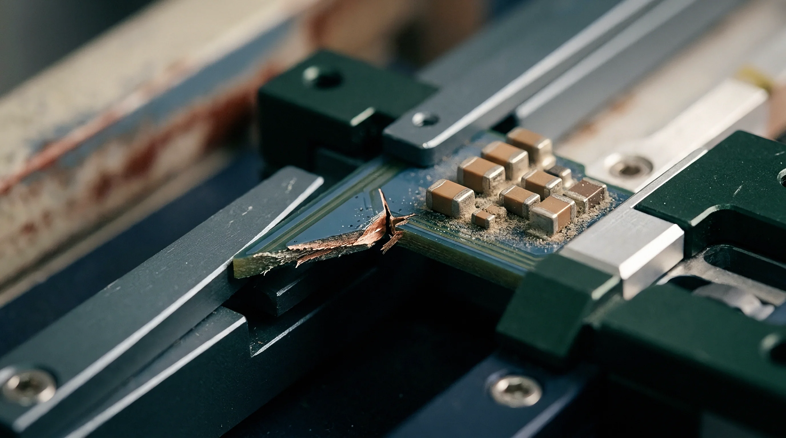
Thermomechanical strain builds up at solder joints where altered copper geometry impairs heat dispersal during power cycling. Unequal copper areas on opposing pads create asymmetric thermal masses, causing one side of a component to reflow ahead of the other and pulling components out of alignment while cracking solder fillets and reducing thermal transfer. This imbalance locks residual mechanical strain into the solder matrix, accelerating fatigue failures in service.
Modeling these mechanical defects requires quantifying localized CTE mismatches and mapping strain energy accumulation across modified SMT joints.
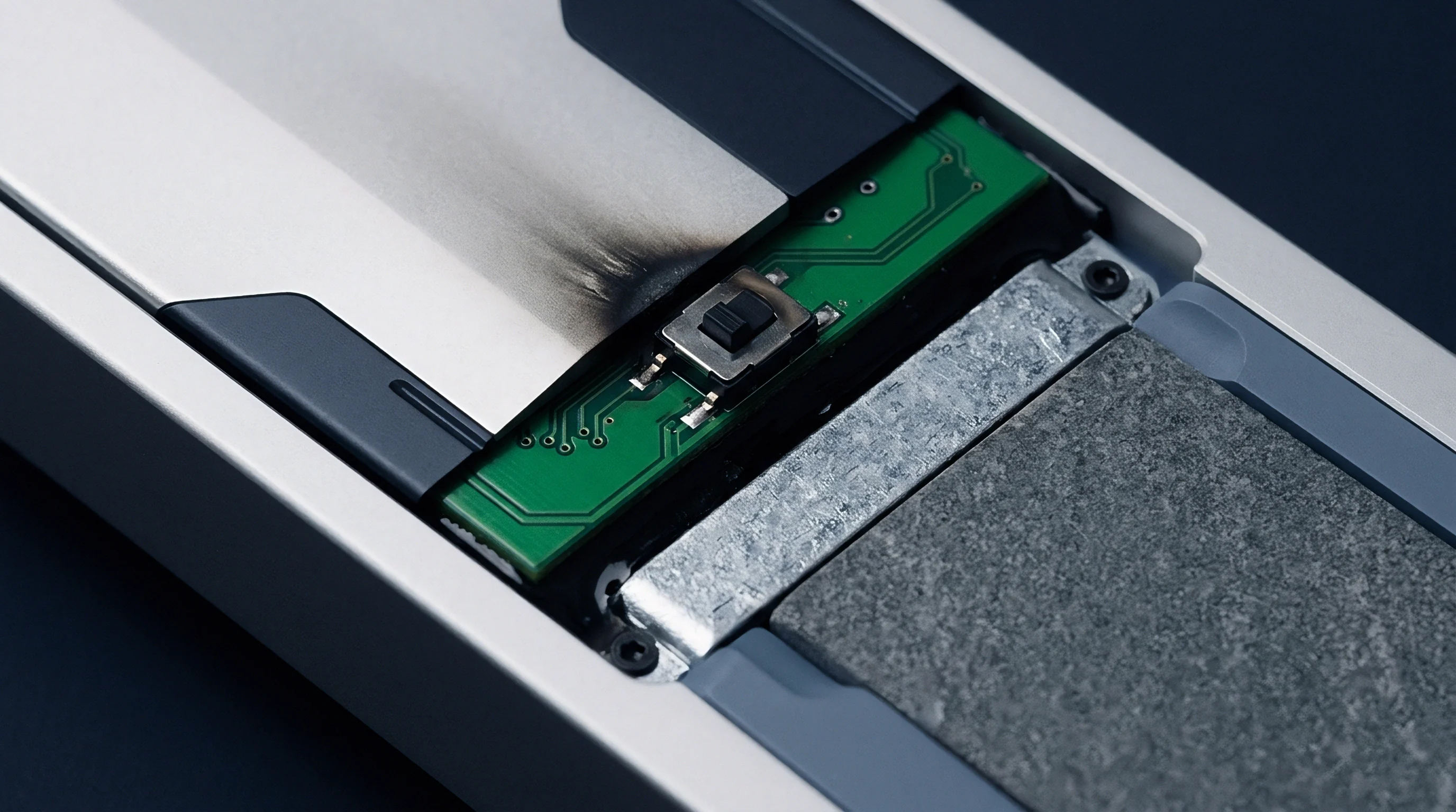
Why Do Thermal Voids Accelerate Joint Fractures?
Differences in the thermal expansion coefficients of FR-4 substrates and ceramic chip components generate steady shear strain across leadless terminations. When manual pad modifications alter the paste volume or its distribution, heat spreads unevenly across the land pattern during reflow. Volatiles from trapped flux form micro-voids in the bulk solder fillet, shrinking the load-bearing area and concentrating mechanical stress along the intermetallic boundary.
Asymmetric thermal relief pads pull molten solder away from narrow signal traces during reflow, creating weak mechanical bonds across surface mount components.
Thermal cycling between minus 40 degrees Celsius and 125 degrees Celsius drives micro-cracks through the beta-tin matrix at these stress concentrations. Extracting a structural defect model involves applying Anand viscoplastic constitutive equations to finite element models of the modified joint geometry to calculate expected operating cycles before solder joint resistance exceeds allowable limits.
- Copper Trace Delamination Mismatched thermal expansion causes modified copper lands to separate from epoxy substrate layers during sustained thermal shock.
- Solder Fillet Micro-Cracking High mechanical stress at modified terminations initiates intermetallic fractures under cyclic thermal loads.
- Thermal Relief Asymmetry Voiding Uneven copper connections draw heat away during reflow, leaving large structural voids in the joint.
- Intermetallic Compound Brittleness Extended dwell times during manual rework build up thick, brittle copper-tin intermetallic layers.
The exact point where accumulated micro-strain transforms stable copper-tin intermetallics into propagating fatigue cracks under continuous vibration remains unsettled for low-halogen resin systems.


Probe
Structural test coverage drops whenever board revisions remove dedicated test points or force spring-loaded probe pins directly onto component leads. Board rework frequently obstructs original test pads, preventing bed-of-nails fixtures and flying probe testers from contacting target nets. Extracting test defect models requires updating fault coverage matrices to account for lost physical access, flagging unprobed copper runs, and remapping boundary scan registers to the modified net topology.

In-Circuit Test Access and Fault Coverage Matrices
Bed-of-nails fixtures depend on target pads of adequate size to measure nodal voltages and verify component placement. When traces are necked down or pads shifted to clear routing bottlenecks, standard 0.8-millimeter test targets often disappear from the netlist. In-circuit test generation tools flag these missing targets as unprobed nodes, lowering the structural fault coverage score for the assembly.
To track the loss of fault detection across modified nets, test engineers update fault dictionary matrices to categorize nodes as fully testable, partially testable, or entirely unprobed.
| Defect Category | Test Method | Fault Coverage Rate (%) | Extraction Complexity | Minimum Clearance (mm) |
|---|---|---|---|---|
| Bridge Under Modified BGA | Automated X-Ray Inspection | 98.5 | High 3D Modeling | 0.15 |
| Open Circuit on Necked Trace | Flying Probe Resistance | 94.2 | Low Coordinate Extraction | 0.25 |
| Unprobed Node Solder Short | Boundary Scan JTAG | 88.0 | Medium Netlist Mapping | 0.00 |
| Intermittent Jumper Resistance | Functional Cluster Test | 72.5 | High SPICE Emulation | 0.50 |
| Fault coverage metrics evaluated under standard IPC-9252 class 2 structural test guidelines using 50-micron flying probe needles. | ||||

Boundary Scan Extraction for Altered Net Topologies
Devices compliant with IEEE 1149.1 run internal boundary scan registers to confirm pin-to-pin connectivity without requiring physical probe contact. When layout changes add active switches, series DC blocking capacitors, or level shifters, they disrupt the scan path. Boundary scan description language (BSDL) files must be updated to match the revised net structures and register cell assignments.
Validating structural integrity across modified SMT nets relies on a defined sequence of physical and software extraction steps.
- Extract updated netlists from the modified CAD database and generate target coordinate files for each SMT node.
- Map probe access paths against mechanical keep-out zones to identify unprobed copper runs across dense component clusters.
- Execute automated flying test routines to measure parasitic resistance variances between modified and reference circuit paths.
- Inject test patterns into boundary scan register cells to identify open traces and shorted surface mount leads.
- Calibrate structural defect fault matrices by correlating measured node voltages against SPICE defect simulations.
Under IPC-9252 section 4.2, unprobed nodes on modified SMT nets lose their automated fault coverage guarantees, returning structural test liability to the design owner.


Scope
Engineering transfer packages define ownership of layout parasitics, physical rework documentation, and updated simulation models between the customer and the manufacturing facility. When a semi-custom program modifies SMT nets, clear contracts determine who pays to extract new defect models, re-qualify test fixtures, and revise manufacturing files. Ambiguity in the scope of work regularly creates unbudgeted non-recurring engineering charges, project delays, and warranty disputes during production ramp.

Design Transfer Packaging and Intellectual Ownership
Supplying complete manufacturing outputs alongside native CAD source files separates proprietary layout IP from standard production deliverables. Turnkey module suppliers often deliver Gerber files while retaining native CAD databases that hold constraint rules and extraction parameters. When board revisions become necessary during bring-up, customers without native source files must pay the original vendor to re-extract parasitics and model structural defects.
Section 7 of the IPC-2581 specification forces turn-key manufacturers to provide native Gerber X2 step files alongside extracted parasitic netlists before design sign-off.
A complete design package for modified nets includes validated schematic netlists, stack-up definitions, 3D parasitic extraction models, updated test coverage reports, and signed rework ECOs. Missing any of these items introduces delays when qualifying second-source manufacturing lines.
| Integration Level | Extracted Defect Artifacts | Engineering Hours | Fee Structure | Change Control Owner |
|---|---|---|---|---|
| Turnkey Reference Module | Basic Gerber Netlist Only | 12 to 24 Hours | Fixed Amortized NRE | Turnkey Factory Owner |
| Semi-Custom Modified Net | Extracted Parasitic SPICE Models | 40 to 80 Hours | Time and Materials NRE | Joint Technical Committee |
| Full Custom SMT Design | Complete S-Parameter & FEA Dossier | 120 to 200 Hours | Itemized Milestone NRE | Client Design Engineering |
| White-Label Build Transfer | IPC-2581 Fabrication & Test Package | 16 to 32 Hours | Included in Tooling Fee | Contract Manufacturer |
Non-Recurring Engineering Arithmetic for Model Extraction
Breaking down engineering hours during module qualification highlights the actual cost structure of turnkey manufacturing support. Parasitic extraction for modified SMT nets requires high-frequency field solvers and custom test fixtures. Billing rates for specialized signal integrity and structural test extraction run between 150 and 225 USD per hour.
A typical extraction campaign for high-speed differential nets on an eight-layer board requires around 60 engineering hours, generating an NRE invoice between 9,000 and 13,500 USD.
If extraction deliverables are not clearly itemized in the initial statement of work, factories bill these engineering tasks as bring-up change orders. Setting these commercial terms before releasing tooling establishes firm budget baselines.
Turnkey contracts that omit explicit parasitic re-extraction fees always shift engineering bring-up risks onto the buyer during product scaling.