Meaning
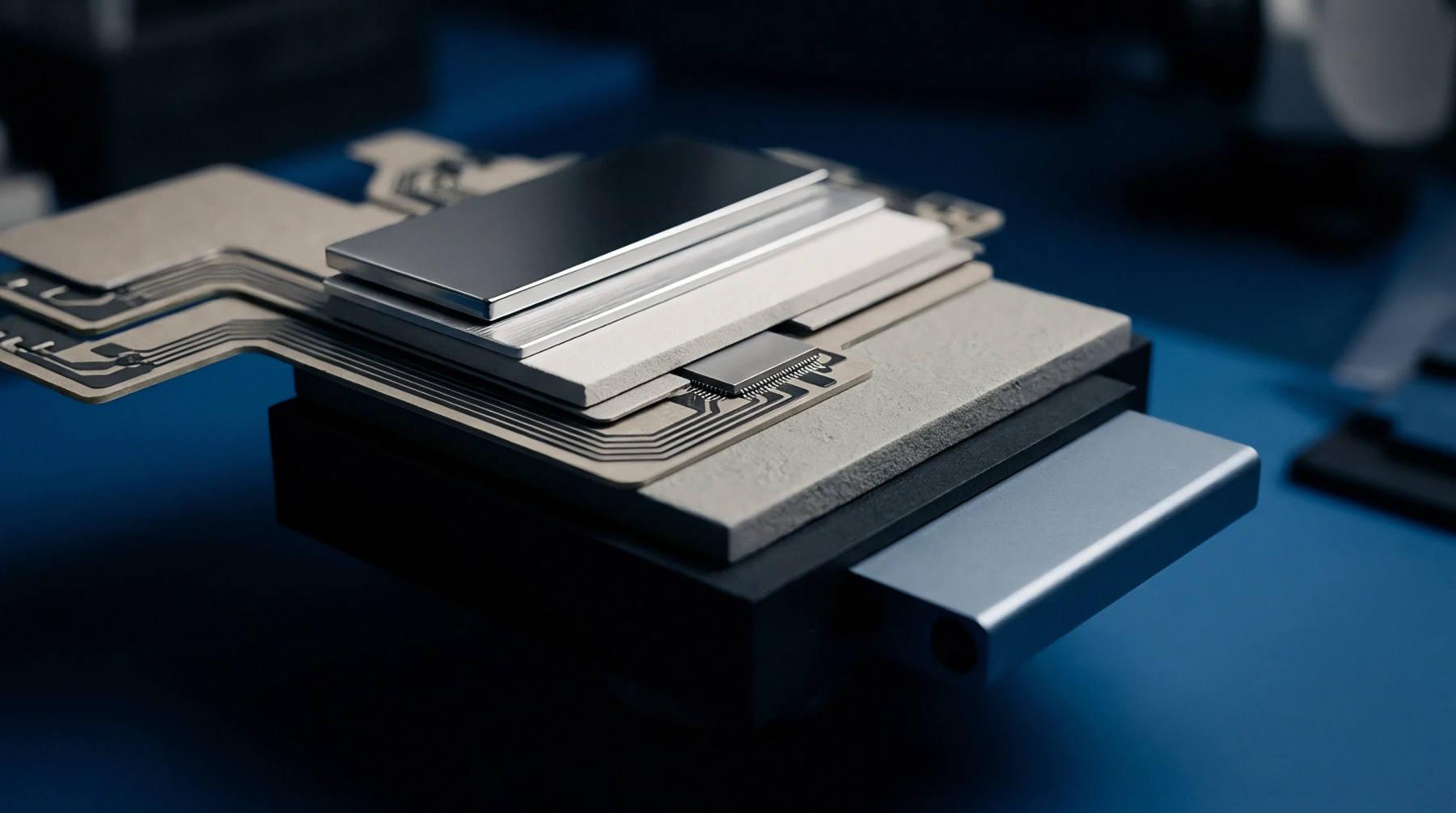
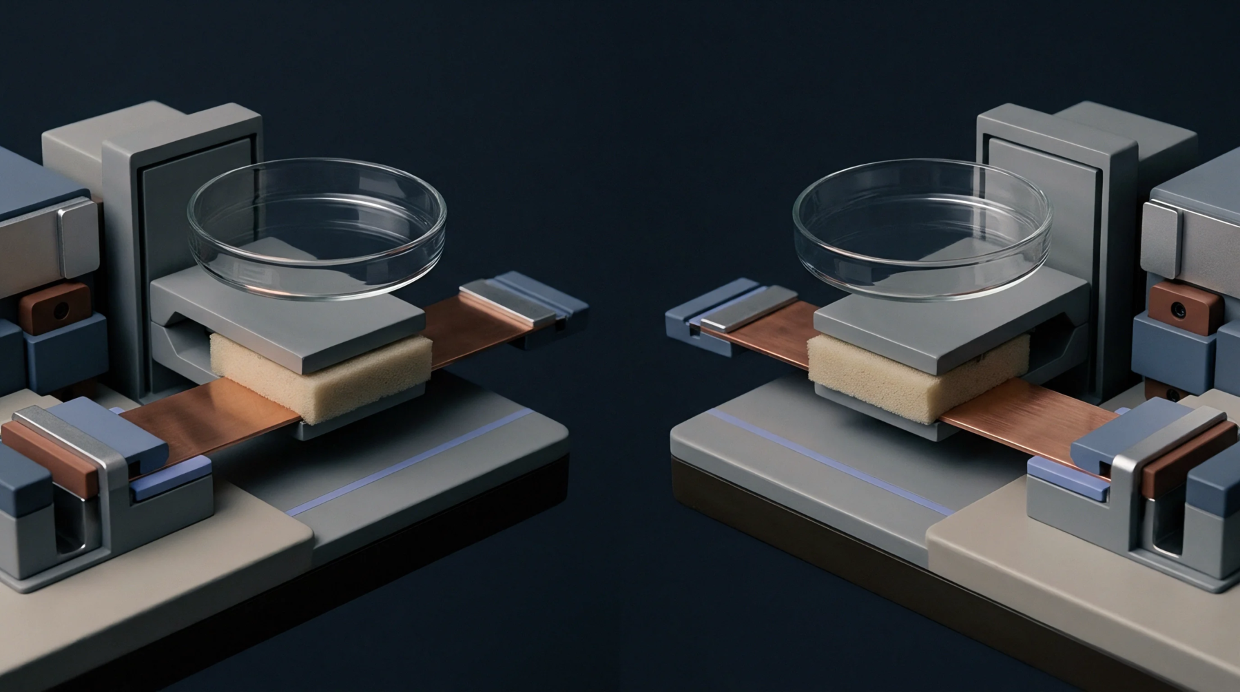
An electromagnetic measurement apparatus employs two identical cylindrical dielectric disks placed in a cavity to determine the permittivity and loss tangent of low-loss substrate materials. A split-post dielectric resonator facilitates non-destructive testing by holding a sample between these posts to induce a specific resonance mode. Operation depends on high-frequency field confinement that minimizes edge effects during characterization.
Resonance Mechanics
The hardware functions by exciting the TE011 mode within the split-post dielectric resonator structure. Electromagnetic energy travels through the air gap and the sample until the frequency stabilizes at a point governed by the dielectric constant of the material. Variations in the shift of the resonant frequency allow for the calculation of complex permittivity.
Accuracy improves as the sample thickness nears the optimal value defined by the disk spacing.
Integration Parameters
Engineers verify the dielectric property data during the material qualification phase of radio frequency board fabrication. Designers select the split-post dielectric resonator to confirm that laminates meet the specified tolerances for signal propagation speed. Measurements obtained through this method provide the values necessary for electromagnetic simulation software models.
Consistent output requires strict thermal control because the resonant frequency of the dielectric disks alters with ambient temperature shifts.
Calibration Constraints
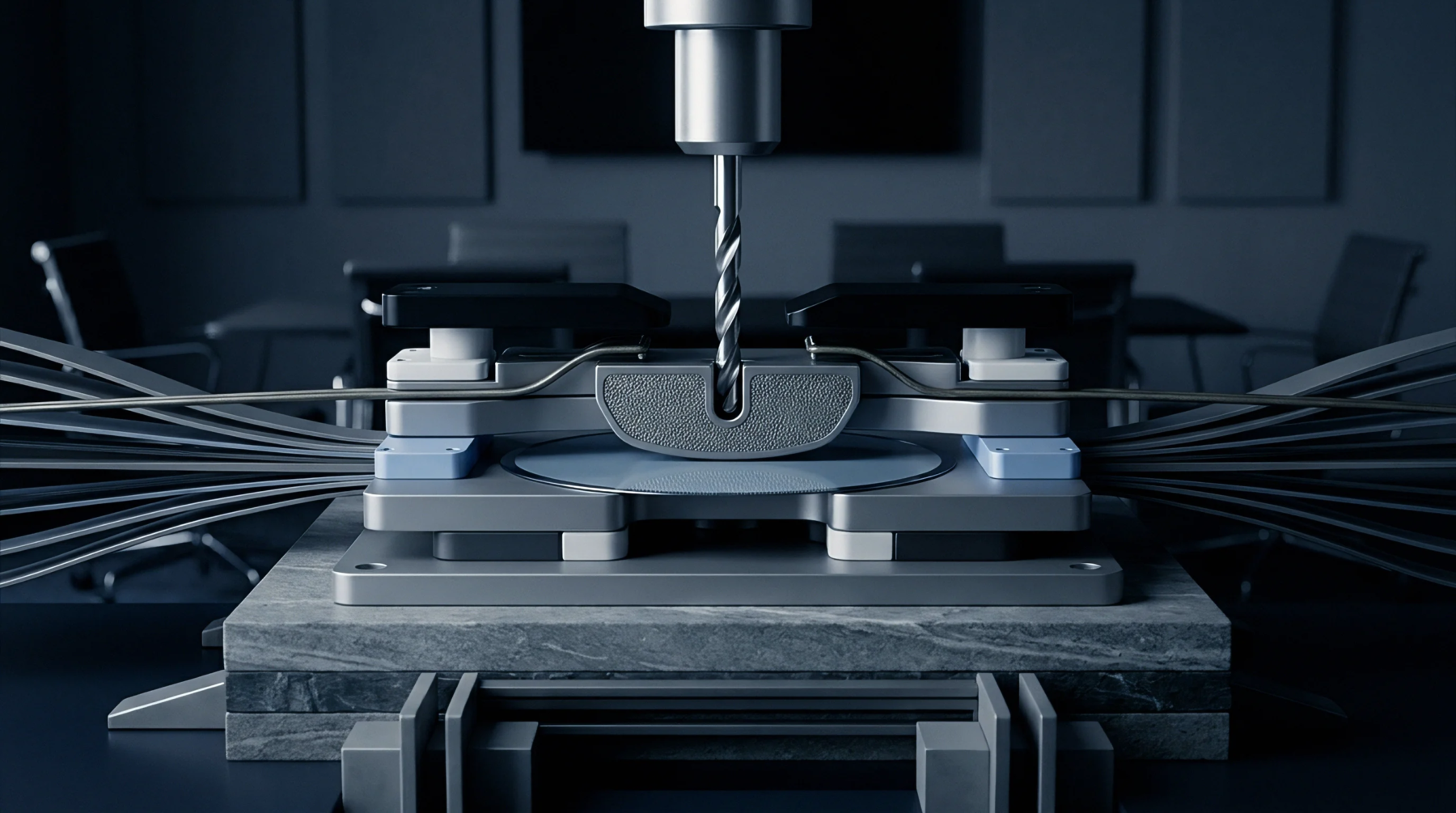
Standard practice dictates that a reference substrate must establish a baseline before the split-post dielectric resonator evaluates production parts. Each measurement cycle accounts for the surface roughness of the material because gaps between the dielectric disks and the sample introduce parasitic reactance. The gap size determines the sensitivity of the measurement device for thin substrates.
Proper calibration ensures that the loss tangent results remain within the operational limits of the intended wireless application.